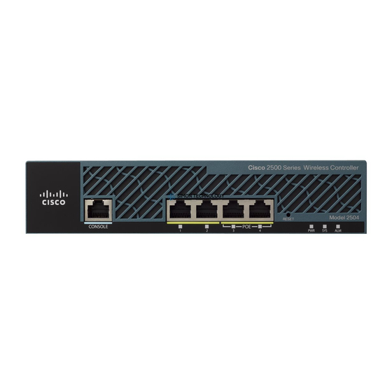
Cisco 2500 Series 설치 매뉴얼 - 페이지 6
{카테고리_이름} Cisco 2500 Series에 대한 설치 매뉴얼을 온라인으로 검색하거나 PDF를 다운로드하세요. Cisco 2500 Series 12 페이지. Wireless controller
Cisco 2500 Series에 대해서도 마찬가지입니다: 구성 매뉴얼 (19 페이지), 배포 매뉴얼 (23 페이지), 구성 매뉴얼 (50 페이지), 시작하기 매뉴얼 (47 페이지)

Replacing the Cover
Figure 6
Screw
Step 3
Figure 7
Replacing the Cover
Take the following steps to replace the cover:
Step 1
Step 2
6 Installing Cisco AC and DC Power Supplies in Cisco 2500 Series Routers
Installing the Screw
0
Connect the power connector from the system board. Grasp the sides of the power
connector and gently push downward while rocking the connector side to side.
(See Figure 7.)
Connecting the Power Connector
Fan
Power connector
Fan connector
Position the two chassis sections, as shown in Figure 8.
Referring to Figure 8, press the two chassis sections together and ensure the following:
•
The top section fits into the rear of the bottom section. (See A in Figure 8.)
•
The bottom section fits into the front of the top section. (See B in Figure 8.)
•
Each side of the top and bottom sections fits together. (See C in Figure 8.)
AC power supply
