Cisco 2811 Series 운영 - 페이지 6
{카테고리_이름} Cisco 2811 Series에 대한 운영을 온라인으로 검색하거나 PDF를 다운로드하세요. Cisco 2811 Series 31 페이지. 2800 series integrated services routers
Cisco 2811 Series에 대해서도 마찬가지입니다: 데이터시트 (20 페이지), 운영 (31 페이지), 설치 및 업그레이드 (14 페이지), 빠른 시작 매뉴얼 (47 페이지)
The Cisco 2811 router features a console port, an auxiliary port, two Universal Serial Bus (USB)
ports, four high-speed WAN interface card (HWIC) slots, two10/100 Gigabit Ethernet RJ45
ports, an Enhanced Network Module (ENM) slot, and a Compact Flash (CF) drive. The 2811
router supports one single-width network module, four single-width or two double-width
HWICs, two slots for AIM-VPN/BPII-Plus cards
(PVDMs), two fast Ethernet connections, and 16 ports of IP phone power output. Figure 2 shows
the front panel and Figure 3 shows the rear panel. The front panel contains 4 LEDs that output
status data about the system power, auxiliary power, system activity, and compact flash busy
status. The back panel consists of 12 LEDs: two Ethernet activity LEDs, two duplex LEDs, two
speed LEDs, two link LEDs, two PVDM LEDs, and two AIM LEDs.
The front panel contains the following:
(1) Power inlet
(2) Power switch
(3) Optional RPS input
(4) Console and auxiliary ports
(5) USB ports
(6) CF drive
(7) LEDs described in table 1.
The back panel contains the following:
(1) Ground connector
(2) and (3) Ethernet ports and LEDs
(4)-(7) HWIC slots
(8) ENM slot.
The following tables provide more detailed information conveyed by the LEDs on the front and
rear panel of the router:
Name
System Power
1
The security policy covers the configuration in which one AIM card is used.
© Copyright 2007 Cisco Systems, Inc.
This document may be freely reproduced and distributed whole and intact including this Copyright Notice.
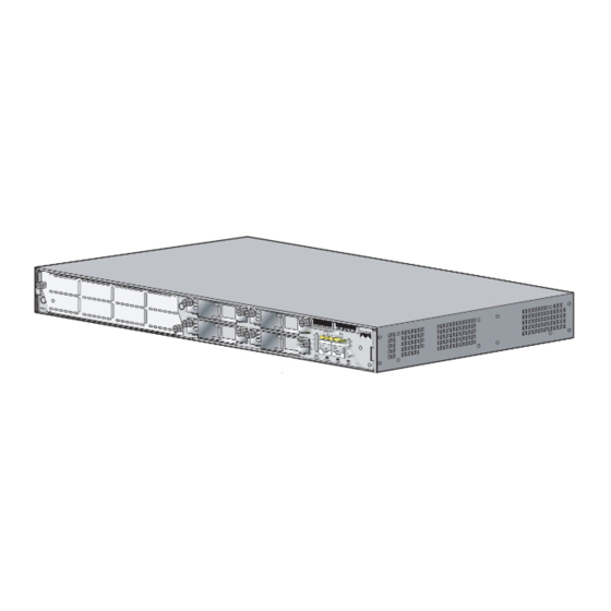
Figure 3 – Rear Panel Physical Interfaces
State
Description
Off
Power off
Blinking Green
ROMMON mode
Solid Green
Operating normally
Solid Orange
System Error Detected
1
, two internal packet voice data modules
6