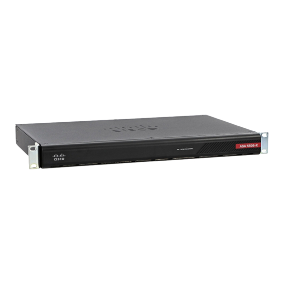
Cisco ASA 5508-X 마운트 및 연결 - 페이지 3
{카테고리_이름} Cisco ASA 5508-X에 대한 마운트 및 연결을 온라인으로 검색하거나 PDF를 다운로드하세요. Cisco ASA 5508-X 6 페이지. Threat defense reimage guide
Cisco ASA 5508-X에 대해서도 마찬가지입니다: 하드웨어 설치 매뉴얼 (32 페이지), 빠른 시작 매뉴얼 (8 페이지), 간편한 설정 매뉴얼 (11 페이지), 빠른 시작 매뉴얼 (9 페이지), 소프트웨어 설명서 (37 페이지), 매뉴얼 (14 페이지)

Mount and Connect
Figure 2: ASA 5508-X and ASA 5516-X Cabling
1
Gigabit Ethernet data interface (RJ-45)
3
Management 1/1 interface (RJ-45)
b) (Optional) Console port – For use with the CLI. Connect a computer or terminal server using a serial console cable
to either the RJ-45 or Mini USB Type B port.
Only one console port can be active at a time. When a cable is plugged into the USB console port, the RJ-45 port
becomes inactive. Conversely, when the USB cable is removed from the Mini USB Type B port, the RJ-45 port
becomes active. See
console port.
c) Gigabit Ethernet ports – For the network interfaces; use standard RJ-45 Ethernet cables.
You can use any available Gigabit Ethernet port on the ASA 5508-X or ASA 5516-X as a failover link. The failover
link interface is not configured as a normal networking interface; it should only be used for the failover link. You
can connect the failover link by using a dedicated switch with no hosts or routers on the link.
Step 2
Connect the power cord to the ASA, and plug the other end to your power source.
Step 3
Press the power switch to turn the appliance on.
When the Power LED is solid green, the ASA is completely powered on.
Step 4
Check the Status LED on the ASA chassis.
When it is solid green, the ASA has passed power-on diagnostics.
Step 5
See the
Cisco ASA 5508-X and ASA 5516-X Quick Start Guide
Connect to a Console Terminal or PC, on page 4
Connect Cables, Turn on Power, and Verify Connectivity
2
Console port (RJ-45 or Mini USB Type B)
for specific instructions for connecting the
to continue setting up your ASA.
Mount and Connect
3
