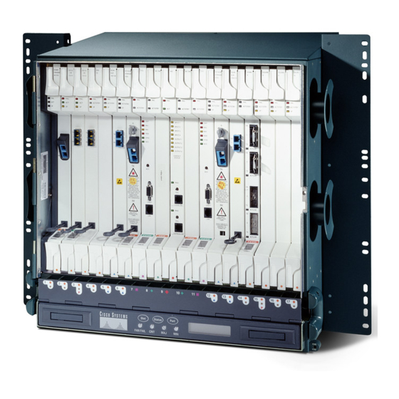
Cisco ONS 15454 설치 - 페이지 21
{카테고리_이름} Cisco ONS 15454에 대한 설치을 온라인으로 검색하거나 PDF를 다운로드하세요. Cisco ONS 15454 32 페이지. Four-shelf and zero-shelf bay assembly
Cisco ONS 15454에 대해서도 마찬가지입니다: 설치 지침 매뉴얼 (22 페이지), 설치 (32 페이지), 포장 풀기 및 설치 (42 페이지), 포장 풀기 및 설치 (40 페이지)

Chapter 1 Install the Shelf and Backplane Cable
Figure 1-7
COM_1
NO_1
COM_3
NO_3
COM_5
NO_5
COM_7
NO_7
COM_9
NO_9
COM_11
NO_11
COM_13
NO_13
COM_15
NO_15
Complete one of the following:
Step 4
If you plan to install electrical cards, continue with the
•
on the Backplane" procedure on page
If you do not plan to install electrical cards, continue with the
•
procedure on page
Stop. You have completed this procedure.
78-18537-01
Alarm Output Connector
Alarm Output
Connector
P4
51
GND1
1
XREF=7
2
3
XREF=7
4
XREF=7
5
XREF=7
6
7
XREF=7
8
XREF=7
9
10
XREF=7
11
XREF=7
12
13
XREF=7
14
15
XREF=7
16
XREF=7
17
XREF=7
18
19
XREF=7
20
XREF=7
21
22
XREF=7
23
XREF=7
24
25
52
GND2
1-23.
NTP- A120 Install an External Wire-Wrap Panel to the AEP
26
XREF=7
27
XREF=7
28
29
XREF=7
30
XREF=7
31
32
XREF=7
33
XREF=7
34
35
XREF=7
36
XREF=7
37
38
XREF=7
39
XREF=7
40
41
XREF=7
42
XREF=7
43
44
XREF=7
45
XREF=7
46
47
XREF=7
48
XREF=7
49
50
"NTP-A9 Install the Electrical Card Cables
1-22.
"NTP-A11 Install the Rear Cover"
Cisco ONS 15454 Procedure Guide, Release 8.5.1
NO_0
COM_0
NO_2
COM_2
NO_4
COM_4
NO_6
COM_6
NO_8
COM_8
NO_10
COM_10
NO_12
COM_12
NO_14
COM_14
1-21
