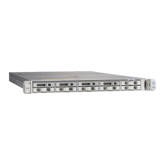
Cisco S695F 하드웨어 설치 매뉴얼 - 페이지 17
{카테고리_이름} Cisco S695F에 대한 하드웨어 설치 매뉴얼을 온라인으로 검색하거나 PDF를 다운로드하세요. Cisco S695F 50 페이지. Web security appliance
Cisco S695F에 대해서도 마찬가지입니다: 시작하기 매뉴얼 (18 페이지), 매뉴얼 (24 페이지)

Overview
The following figure shows the rear panel of the WSA S695. See
of the LEDs.
Figure 11: S695 Rear Panel
1
Proxy port 1 (P1)
Connects to the network for both incoming and
outgoing traffic.
3
Traffic monitor port 1 (T1)
Use for Duplex Ethernet tap; one cable for all
incoming and outgoing traffic.
5
1050-W AC power supply (PSU 1)
7
Threaded holes for dual-hole grounding lug
Use is optional. The supported AC power supplies
have internal grounding, so no additional chassis
grounding is required.
9
USB 3.0 Type A (USB 2)
Management interface 2 (MGMT 2)
11
Not in use
13
Serial console port (Console)
RJ-45 connector that directly connects a
management computer to the appliance.
The following figure shows the rear panel of the WSA S695F. See
description of the LEDs.
Cisco Web Security Appliance S195, S395, S695, and S695F Hardware Installation Guide
Rear Panel LEDs, on page 15
2
Proxy port 2 (P2)
When P1 and P2 are both enabled, you must
connect P1 to the internal network and P2 to the
internet.
Note
You can connect P1 and P2 to an L4
switch, WCCP router, or network
switch.
4
Traffic monitor port 2 (T2)
Use for Simplex Ethernet tap; one cable connected
to T1 for all packets going to the internet. and one
cable connected to T2 for all packets coming from
the internet.
6
1050-W AC power supply (PSU 2)
8
USB 3.0 Type A (USB 1)
10
Management interface 1 (MGMT 1)
Restricted to management use only
RPC port (RPC)
12
Use for remote power cycling.
14
Unit identification button
Rear Panel LEDs, on page 15
Rear Panel
for a description
for a
13
