Cisco SCE8000 GBE 빠른 시작 매뉴얼 - 페이지 6
{카테고리_이름} Cisco SCE8000 GBE에 대한 빠른 시작 매뉴얼을 온라인으로 검색하거나 PDF를 다운로드하세요. Cisco SCE8000 GBE 25 페이지. 10gbe platform
Cisco SCE8000 GBE에 대해서도 마찬가지입니다: 구성 매뉴얼 (18 페이지), 제거 및 교체 절차 (36 페이지), 설치 (21 페이지)
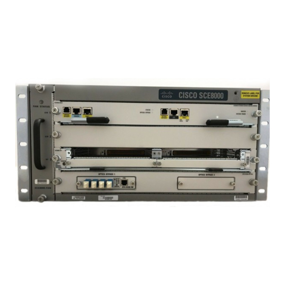
Figure 3
Optical Bypass Modules in External Mounting Panel
FA N ST
SCE 8000
AT US
-SCM -E
SC M
1
OPT ICAL
BYP ASS
CON SOL
E
POR T 1
10 100
LINK
1000
ACTI VE
SCE 8000
-SCM -E
SC M
2
OPT ICAL
BYP ASS
CON SOL
E
POR T 1
10 100
LINK
1000
ACTI VE
SCE 8000
-SIP
3
SIP
4
SC E8 00
0- FA N
3
Connecting Power Supply Units
The SCE8000 chassis is shipped with the power supplies (AC or DC) already installed. This section provides information for
grounding the SCE8000 platform and connecting the AC or DC power supply units.
Connecting the Chassis Ground
If this equipment is installed in a U.S. or European Central Office, you must connect the system ground on both AC
Note
and DC-powered systems to an earth ground.
Note
For DC-powered systems, the system ground is also the power supply ground. The DC ground must be installed with
a permanent connection to an earth ground according to NEC guidelines.
When you use the PWR-2700-DC/4 power supply in the Cisco SCE8000 chassis, additional grounding requirements
Note
exist.
Two threaded M4 holes are provided on the chassis frame to attach the ground cable.
6
STA TUS
OPT ICA
L BYP ASS
SCE8 000
EXTE NDED
SERV ICE
CON TROL
MOD ULE
MA STE R
SYS TEM
POW ER
STA TUS
OPT ICA
L BYP ASS
SCE8 000
EXTE NDED
SERV ICE
CON TROL
MOD ULE
MA STE R
SYS TEM
POW ER
SPA -1X1
0GE -L-V2
SPA -1X1
0GE -L-V2
SPA -1X1
0GE -L-V2
SPA -1X1
0GE -L-V2