Cisco ASR 5000 설치 매뉴얼
{카테고리_이름} Cisco ASR 5000에 대한 설치 매뉴얼을 온라인으로 검색하거나 PDF를 다운로드하세요. Cisco ASR 5000 18 페이지. Applying power and verifying the installation
Cisco ASR 5000에 대해서도 마찬가지입니다: 설치 매뉴얼 (33 페이지), 설치 절차 (8 페이지), 설치 매뉴얼 (37 페이지)
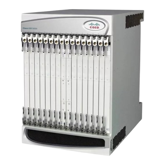
Chassis Installation
This chapter provides information on rack configurations and instructions for installing and removing the
chassis and its sub-components – the upper and lower fan trays and the Power Filter Units (PFUs).
Important
This chapter includes the following sections:
•
•
•
•
Equipment Rack Configuration
The chassis is designed for installation in a standard 19-inch (48.26 cm) equipment rack. Additional rack
hardware, such as extension brackets, may be used to install the chassis in a standard 23-inch (58.42 cm) rack.
Each chassis is 24.50 inches (62.23 cm) high. This equates to roughly 14 Rack Mount Units (RMUs: 1 RMU
= 1.75 in (4.45 cm).
You can mount a maximum of three chassis in a standard 48 RMU (7 ft.) equipment rack or telco cabinet
provided that all system cooling and ventilation requirements are met. A fully-loaded rack with three chassis
installed has approximately 5.5 inches (13.97 cm, 3.14 RMUs) of vertical space remaining.
When planning chassis installation, take care to ensure that the equipment rack or cabinet hardware does
Caution
not hinder air flow at any of the intake or exhaust vents. Additionally, ensure that the environmental control
system (HVAC) allows the system to function within the required limits.
Prior to installation, personnel should review and be familiar with all recommendations for Central Office
installations, as found in Telcordia GR-1275-CORE Central Office Environment Installation/Removal
Generic Requirements, Issue 3, December 2001.
Equipment Rack Configuration, page 1
Weight Considerations, page 3
Unpacking the ASR 5000 Chassis, page 3
Installing the Chassis, page 6
ASR 5000 Installation Guide
1