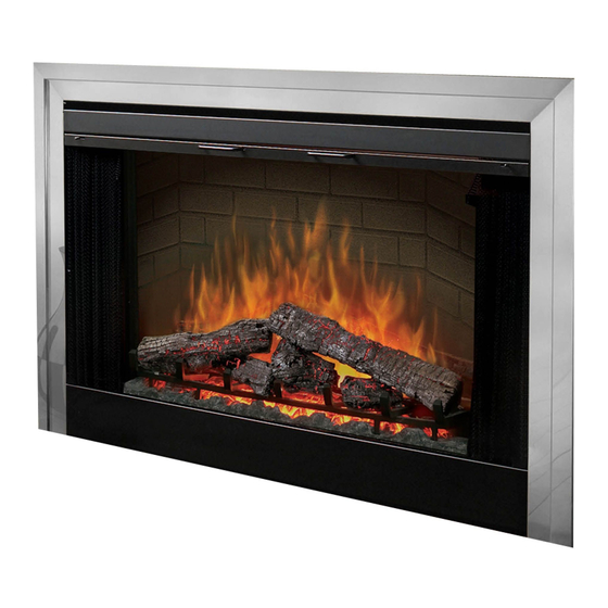
Dimplex BF36ST 서비스 매뉴얼 - 페이지 9
{카테고리_이름} Dimplex BF36ST에 대한 서비스 매뉴얼을 온라인으로 검색하거나 PDF를 다운로드하세요. Dimplex BF36ST 13 페이지. Optiflame electric fireplace
Dimplex BF36ST에 대해서도 마찬가지입니다: 설치 매뉴얼 (10 페이지)

firebox and remove the top cover by lifting it up from the
back, bowing it slightly in the center and pulling out by
one end.
4. Locate the elements mounted to the top cover and dis-
connect the connections noting their original locations.
5. Bend the open end of the element retaining bracket just
enough so the element can be removed.
6. Remove the element by pulling down and out from the
loose end of the retaining bracket.
7. Properly orient the replacement element and connect all
of the wiring connections in their original locations.
8. Reassemble in the reverse order as above.
Blower Motor/Blower Replacement
Tools Required: Philips head screwdriver
Flat head screwdriver
WARNING: If the fireplace was operating prior to servic-
ing, allow at least 10 minutes for light bulbs and heating ele-
ments to cool off to avoid accidental burning of skin.
WARNING: Disconnect power before attempting any
maintenance to reduce the risk of electric shock or damage
to persons.
1. Open the steel curtains (remove glass doors if appli-
cable).
2. Remove the steel curtains by lifting up on the curtain
mounting rod releasing it from the side mounting tab, and
pulling out.
3. Remove the top cover mounting screws from inside the
firebox and remove the top cover by lifting it up from the
back, bowing it slightly in the center and pulling out by
one end.
!
NOTE: A new rubber channel that holds the partially re-
flective glass in place is supplied with the new blower motor.
4. Hold the partially reflective glass and use a sharp utility
knife to cut the lip off of the rubber channel (one side
only) that holds in the partially reflective glass in place.
5. Remove partially reflective glass by pulling it out of the
cut rubber channel being careful not to bump or drop it.
6. Remove the cut channel from the firebox.
7. Locate the motor/blower assembly at the top of the fire-
box; disconnect the motor wiring connections noting their
original locations.
8. Grasp the motor and turn ¼ of a turn up, towards the top
of the firebox to release it from the blower assembly.
9. Hold the blower and pull the motor assembly drive shaft
out of the blower.
10. Properly orient the replacement motor and connect all of
the wiring connections in their original locations.
11. Reassemble in the reverse order as above.
!
NOTE: To install the partially reflective glass after the
factory installed rubber channel has been cut, use the chan-
nel that was supplied with the replacement motor / blower.
Slide the channel onto the edge of the partially reflective
glass and push the other side of the partially reflective glass
into the existing rubber channel in the firebox, carefully press
partially reflective glass into the mounting slot on the firebox.
Temperature Limit Switch Replacement
Tools Required: Philips head screwdriver
Flat head screwdriver
WARNING: If the fireplace was operating prior to servic-
ing, allow at least 10 minutes for light bulbs and heating ele-
ments to cool off to avoid accidental burning of skin.
WARNING: Disconnect power before attempting any
maintenance to reduce the risk of electric shock or damage
to persons.
!
NOTE: The fireplace is equipped with two heating ele-
ments. The same removal & installation instructions apply to
both elements.
1. Open the steel curtains (remove glass doors if appli-
cable).
2. Remove the steel curtains by lifting up on the curtain
mounting rod at the side releasing it from the mounting
tab, and pulling out.
3. Remove the top cover mounting screws from inside the
firebox and remove the top cover by lifting it up from the
back, bowing it slightly in the center and pulling out by
one end.
4. Locate the elements mounted to the top cover.
5. Bend the open end of the element retaining brackets just
enough so the element can be removed.
6. Remove the element by pulling down and out from the
loose end of the retaining bracket being careful not to
damage any of the wiring.
7. Locate the temperature limit switch mounted to the roof
plate under the elements.
8. While holding onto the switch with needle nose pliers, re-
move the mounting screw for the temperature limit switch
and pull it out of the top cover.
9. Disconnect the wiring connections located behind the
blower assembly and remove the switch.
10. Properly orient the replacement temperature limit switch
and connect all of the wiring connections in their original
locations.
11. Reassemble in the reverse order as above.
Remote Control Receiver Replacement
Tools Required: Philips head screwdriver
Flat head screwdriver
WARNING: If the fireplace was operating prior to servic-
ing, allow at least 10 minutes for light bulbs and heating ele-
ments to cool off to avoid accidental burning of skin.
WARNING: Disconnect power before attempting any
maintenance to reduce the risk of electric shock or damage
to persons.
1. Open the steel curtains (remove glass doors if appli-
cable).
2. Remove the log grate retaining screws and remove the
log grate.
9
