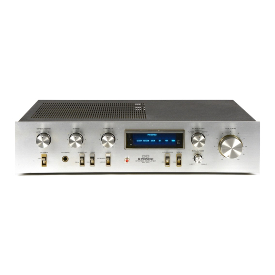
Pioneer SA-710 서비스 매뉴얼 - 페이지 3
{카테고리_이름} Pioneer SA-710에 대한 서비스 매뉴얼을 온라인으로 검색하거나 PDF를 다운로드하세요. Pioneer SA-710 10 페이지.
Pioneer SA-710에 대해서도 마찬가지입니다: 사용 설명서 (13 페이지)

3 . S C H E M A T I C D I A G R A M
X L L
TAPE 1
P L A Y
R E C
TAPE 2
P L A Y
T U N E R
I r 5 o ; t l
A U X
F 5 o ' v l
A U X
T U N E R
P L A Y
T A P E 2
R E C
P H O N O
Es"tl
I
I
I
|
" " : "
I
raPE 1
t
R E c
A F A M P A s s ' Y ( l / 2 )
G W K - 1 5 2
- -tt
t"-oFo ,nt."t&;i-
I
A S H - 0 1 6
5 4 : L o U O N E S S C 2 9
q s , e 2 S A 9 1 2
v R t - 2
r o o r
1 . R E S I S T O R S :
f ndicated in a, y.W, !5% tolerance unless otherwise noted k : kQ,
M : M o ,
( F ) : t l % , ( G ) : r 2 % , ( K ) r t l O % t o l e r a n c e
2 . C A P A C I T O R S :
Indicated in capacity (!F)/voltage (V) unless othemise noted p : pF
Indication without
voltage is 50V
except elmtrolytic
capacitor.
3 . V O L T A G E , C U R R E N T :
[
: S i g n a l v o l t a g e a t
6 5
W + 6 5
w
8 r l o u t p u t ( 1 k H z )
[
: D C v o l t a g e ( V ) a t n o i n p u t s i g n a l
Value in (
) is DC voltage at rated power.
.fu
mA : DC current at no input signal
4 . O T H E R S :
+ :
S i g n a l r o u t e .
A
: A d j u s t i n g p o i n t .
The
I
mark tound on some component parts indicates the rm-
portance of the satety factor ol the part. Therefore, when replacing,
be sure to use parts of identical designation.
This is the basic shematic diagram, but the actual circuit may vary
due to improvements in design.
3 . 9 k ( F ) 4 8 . 7 1 ( F )
C 2 3
C 2 l
2 2 / 5 0
0 . O 4 '
q r , z 2 S A 9 7 8
q r , c 2 S C l 7 7 5 A
3 . 9 r ( F ) 1 4 8 . 7 r ( F )
c 3 l
o. 056
[ - .
! i
P O W E R S U P P L Y C I R C U I T F O R H B M O D E L
o w x - r s z j
I
I
I R E O
I
I
I
I
I
- - - J
F U S E A s s ' y
G W X - 4 8 8
