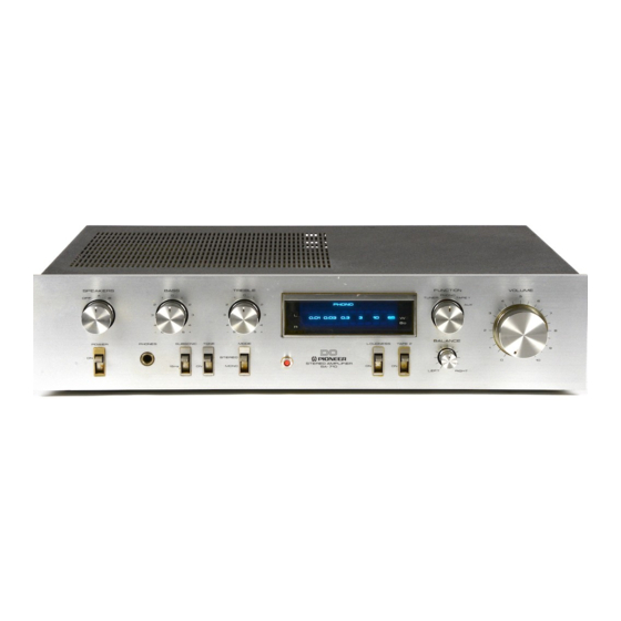
Pioneer SA-710 Instrukcja serwisowa - Strona 3
Przeglądaj online lub pobierz pdf Instrukcja serwisowa dla Wzmacniacz Pioneer SA-710. Pioneer SA-710 10 stron.
Również dla Pioneer SA-710: Instrukcja obsługi (13 strony)

3 . S C H E M A T I C D I A G R A M
X L L
TAPE 1
P L A Y
R E C
TAPE 2
P L A Y
T U N E R
I r 5 o ; t l
A U X
F 5 o ' v l
A U X
T U N E R
P L A Y
T A P E 2
R E C
P H O N O
Es"tl
I
I
I
|
" " : "
I
raPE 1
t
R E c
A F A M P A s s ' Y ( l / 2 )
G W K - 1 5 2
- -tt
t"-oFo ,nt."t&;i-
I
A S H - 0 1 6
5 4 : L o U O N E S S C 2 9
q s , e 2 S A 9 1 2
v R t - 2
r o o r
1 . R E S I S T O R S :
f ndicated in a, y.W, !5% tolerance unless otherwise noted k : kQ,
M : M o ,
( F ) : t l % , ( G ) : r 2 % , ( K ) r t l O % t o l e r a n c e
2 . C A P A C I T O R S :
Indicated in capacity (!F)/voltage (V) unless othemise noted p : pF
Indication without
voltage is 50V
except elmtrolytic
capacitor.
3 . V O L T A G E , C U R R E N T :
[
: S i g n a l v o l t a g e a t
6 5
W + 6 5
w
8 r l o u t p u t ( 1 k H z )
[
: D C v o l t a g e ( V ) a t n o i n p u t s i g n a l
Value in (
) is DC voltage at rated power.
.fu
mA : DC current at no input signal
4 . O T H E R S :
+ :
S i g n a l r o u t e .
A
: A d j u s t i n g p o i n t .
The
I
mark tound on some component parts indicates the rm-
portance of the satety factor ol the part. Therefore, when replacing,
be sure to use parts of identical designation.
This is the basic shematic diagram, but the actual circuit may vary
due to improvements in design.
3 . 9 k ( F ) 4 8 . 7 1 ( F )
C 2 3
C 2 l
2 2 / 5 0
0 . O 4 '
q r , z 2 S A 9 7 8
q r , c 2 S C l 7 7 5 A
3 . 9 r ( F ) 1 4 8 . 7 r ( F )
c 3 l
o. 056
[ - .
! i
P O W E R S U P P L Y C I R C U I T F O R H B M O D E L
o w x - r s z j
I
I
I R E O
I
I
I
I
I
- - - J
F U S E A s s ' y
G W X - 4 8 8
