Alderon Industries Versa'larm VA01A 운영, 유지보수 및 설치 매뉴얼 - 페이지 4
{카테고리_이름} Alderon Industries Versa'larm VA01A에 대한 운영, 유지보수 및 설치 매뉴얼을 온라인으로 검색하거나 PDF를 다운로드하세요. Alderon Industries Versa'larm VA01A 4 페이지. 1 zone alarm
Alderon Industries Versa'larm VA01A에 대해서도 마찬가지입니다: 운영, 유지보수 및 설치 매뉴얼 (4 페이지)

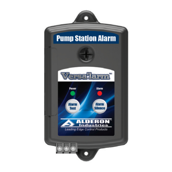
Versa'larm
1-Zone Alarm - Model VA01A
Operation, Maintenance and Installation Manual
Installation of the Alarm Panel Continued
7. Connect any combination of switches (rated 9 VDC, 200mA Minimum) such as a float switch, water sensor, or sump probe
sensor to Terminals C and 1 on the terminal block of the alarm panel. TERMINAL 2 IS NEVER USED. See below for wiring
examples (Fig. 13). The alarm is activated by a "closed" switch. CAUTION! - When installing the "Signaling Device", refer to
its installation instructions for proper installation.
TERMINALS C AND 1:
Float Switch
Black = 1
White = C
WaterSpotter™ or WaterSpotter™ Probe
Black = 1
Red = C
Combination of Sensors
Blacks = 1
Reds / Whites = C
Versa'larm
Accessory (P/N: 7933)
™
Indoor/Outdoor LED Strobe Beacon
Use 18 gauge wire and connect Red Wire
to Terminal C and Black Wire to Terminal 2
8. Plug the alarm panel power supply into a 120 VAC, 50/60 Hz standard
wall outlet and the green "Power" LED should illuminate (Fig. 14).
Testing the Alarm Panel
1. Test the alarm panel by pressing and holding the "Alarm Test" pushbutton
(Fig. 15) or activating the "Signaling Device" (i.e., float switch or water
sensor / Fig. 16). The buzzer should annunciate and the alarm LED should
illuminate. Press the "Alarm Silence" pushbutton and the buzzer should
silence while the alarm LED remains on. After you remove pressure from
the "Alarm Test" pushbutton or deactivate the "Signaling Device", the "Auto
Reset" feature reactivates the alarm panel for the next alarm cycle. If testing
with "Signaling Device", make sure to test all devices for complete system
operation. Test product weekly to ensure system integrity.
Alarm Systems
Control Panels
Alderon Industries - Hawley, MN | 218.483.3034 | [email protected] | alderonind.com
™
X
Float Switch
White = C
Black = 1
Float Switches
Leak Detection Systems
(Fig. 13)
X
Float Switch
WaterSpotter™
White = C
Red = C
Black = 1
Black = 1
(Fig. 15)
X
Float Switch
White = C
Black = 1
WaterSpotter™
Red = C
WaterSpotter™ Probe
Black = 1
Red = C
Black = 1
(Fig. 14)
5 ft. Max
(Fig. 16)
P/N: 101444
Page 4 of 4
