Yamaha Electone HS-8 서비스 매뉴얼 - 페이지 17

{카테고리_이름} Yamaha Electone HS-8에 대한 서비스 매뉴얼을 온라인으로 검색하거나 PDF를 다운로드하세요. Yamaha Electone HS-8 43 페이지. Serie hs monitor da studio alimentato e subwoofer alimentato
Yamaha Electone HS-8에 대해서도 마찬가지입니다: 소유자 매뉴얼 (2 페이지), 소유자 매뉴얼 (2 페이지), 소유자 매뉴얼 (20 페이지), 소유자 매뉴얼 (20 페이지), 소유자 매뉴얼 (21 페이지), 소유자 매뉴얼 (20 페이지), 소유자 매뉴얼 (20 페이지), 소유자 매뉴얼 (20 페이지), 소유자 매뉴얼 (20 페이지), 소유자 매뉴얼 (20 페이지), 소유자 매뉴얼 (20 페이지), 소유자 매뉴얼 (20 페이지), 소유자 매뉴얼 (20 페이지), (영어) 사용 설명서 (20 페이지)
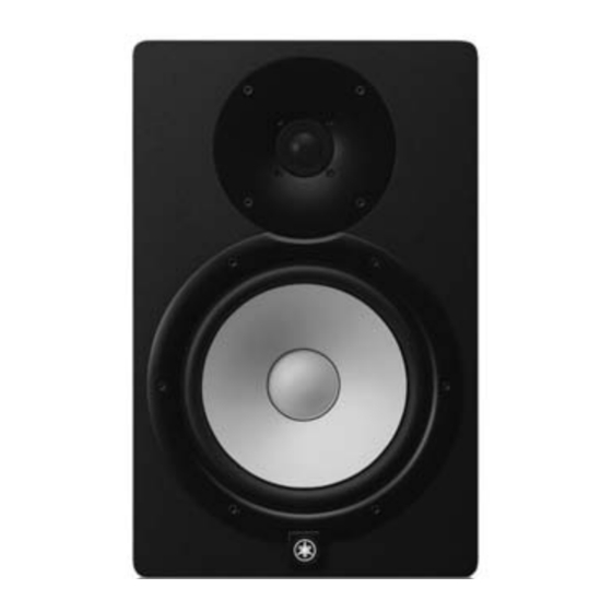
Yamaha Electone HS-8 서비스 매뉴얼
INSPECTIONS
AMP assembly test
1 Measurement conditions
1-1
Power Source
Destination
J
100V +2/-0V
120V +2/-0V
U
E
230V +2/-0V
240V +2/-0V
A
1-2
Measuring Instruments
The measuring instruments shall have accuracy and
precision enough to measure the spec of each charac
teristic to be inspected.
The input impedance of the measuring instruments
shall be 100kΩ or more.
Use the JIG and the measuring instrument that can mea
sure the specifi cation value described to this document.
1-2-1 Connection
Each signal I/O terminal is as shown in the FIG.1.
FIG. 1 : IO TERMINAL
Voltage
Frequency
50/60Hz
60Hz
50Hz
50Hz
INPUT 1 (XLR)
INPUT 2 (PHONE)
SPOUT (HF)
SPOUT (LF)
LED OUT (W401)
2 Electric characteristics
2-1
Preparation
The load resistances for each output terminals are as fol-
lows.
SPOUT
LF:
Between 205 terminal (wire color: RED) and 110
terminal (wire color: BLACK) of WIRING ASSY
SPOUT.
: 4 ohms±1% (Rated 100W or more)
HF:
Between 205 terminal (wire color: Yellow) and 110
terminal (wire color: Blue) of WIRING ASSY
SPOUT.
: 8 ohms±1% (Rated 50W or more)
Unless otherwise specifi ed, the operation should be
set as follows.
LEVEL control
ROOM CONTROL switch : 0
HIGH TRIM switch
Unless otherwise specifi ed, the LF input signal
should be 1 kHz sine wave and the HF input signal
should be 10 kHz sine wave.
The input signal impedance should be 100-150
ohms.
0dBu is referenced to 0.775Vrms. 0dBV is refer
enced to 1Vrms.
2-2
Inspection
2-2-1 Gain
Measurement condition
The signal of -10dBu is input to
INPUT 1(XLR), and the output
voltage is measured.
The signal of -10dBu is input
to INPUT 2(PHONE), and the
output voltage is measured.
The signal of -10dBu is input to
INPUT 1 (XLR), and the output
voltage is measured.
HS8/HS7/HS5
: -10dB (MAX)
: 0
Criteria
+20.7 ± 2 dBu
SPOUT (LF)
+21.0 ± 2 dBu
Red-Black
+18.7 ± 2 dBu
+25.7 ± 2 dBu
SPOUT (HF)
+23.0 ± 2 dBu
Yellow-Blue
+21.0 ± 2 dBu
17