Yamaha Electone HS-8 서비스 매뉴얼 - 페이지 18

{카테고리_이름} Yamaha Electone HS-8에 대한 서비스 매뉴얼을 온라인으로 검색하거나 PDF를 다운로드하세요. Yamaha Electone HS-8 43 페이지. Serie hs monitor da studio alimentato e subwoofer alimentato
Yamaha Electone HS-8에 대해서도 마찬가지입니다: 소유자 매뉴얼 (2 페이지), 소유자 매뉴얼 (2 페이지), 소유자 매뉴얼 (20 페이지), 소유자 매뉴얼 (20 페이지), 소유자 매뉴얼 (21 페이지), 소유자 매뉴얼 (20 페이지), 소유자 매뉴얼 (20 페이지), 소유자 매뉴얼 (20 페이지), 소유자 매뉴얼 (20 페이지), 소유자 매뉴얼 (20 페이지), 소유자 매뉴얼 (20 페이지), 소유자 매뉴얼 (20 페이지), 소유자 매뉴얼 (20 페이지), (영어) 사용 설명서 (20 페이지)
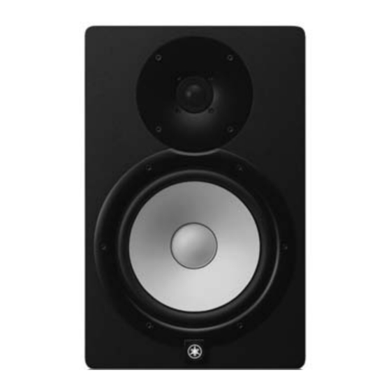
Yamaha Electone HS-8 서비스 매뉴얼
HS8/HS7/HS5
2-2-2 Maximum Output
Measurement condition
Criteria
The following outputs are obtained, total har-
monic distortion is measured.
The signal is input to
the INPUT 1 (XLR).
SPOUT (LF)
Red-Black
The following outputs are obtained, total har-
monic distortion is measured.
The signal is input to
the INPUT 1 (XLR).
SPOUT (HF)
Yellow-Blue
* Measure this inspection within 5 seconds.
2-2-3 Total Harmonic Distortion
Measurement condition
Criteria
The following outputs are obtained, total har-
monic distortion is measured.
The signal is input to
the INPUT 1 (XLR).
SPOUT (LF)
Red-Black
The following outputs are obtained, total har-
monic distortion is measured.
The signal is input to
the INPUT 1 (XLR).
SPOUT (HF)
Yellow-Blue
18
HS8
THD + N =
Min +23.6 dBu
1% or less.
HS7
THD + N =
Min +22.4 dBu
1% or less.
HS5
THD + N =
Min +20.0 dBu
1% or less.
HS8
THD + N =
Min +26.1 dBu
1% or less.
HS7
THD + N =
Min +25.1 dBu
1% or less.
HS5
THD + N =
Min +23.3 dBu
1% or less.
HS8
THD + N =
+21.0 ± 0.2 dBu
0.2% or less.
HS7
THD + N =
+20.1 ± 0.2 dBu
0.2% or less.
HS5
THD + N =
+18.8 ± 0.2 dBu
0.2% or less.
HS8
THD + N =
+21.8 ± 0.2 dBu
0.2% or less.
HS7
THD + N =
+20.7 ± 0.2 dBu
0.2% or less.
HS5
THD + N =
+19.3 ± 0.2 dBu
0.2% or less.
2-2-4 Frequency Response
Measurement condition
The signal of -20dBu is input to
INPUT 1(XLR), and the output
voltage is measured.
The signal of -10dBu is input to
INPUT 1(XLR), and the output
voltage is measured.
1.7kHz
-20dBu
47.0Hz
-20dBu
1.8kHz
-20dBu
51.0Hz
-20dBu
Each signal is
input to INPUT
1.7kHz
1(XLR), and the
-20dBu
output voltage is
measured.
65.0Hz
-20dBu
2.9kHz
-10dBu
2.7kHz
-10dBu
3.1kHz
-10 dBu
Criteria
A1
SPOUT(LF)
A2
Red-Black
A3
A4
SPOUT(HF)
A5
Yellow-Blue
A6
T h e r a n g e
of -3.0±2dB
based on A1.
The range of
+ 9 . 9 ± 2 d B
based on A1.
T h e r a n g e
of -3.0±2dB
based on A2.
SPOUT(LF)
Red-Black
The range of
+ 5 . 8 ± 2 d B
based on A2.
The range of
-3±2dB based
on A3.
The range of
+ 4 . 5 ± 2 d B
based on A3.
T h e r a n g e
of -3.0±2dB
based on A4.
T h e r a n g e
SPOUT(HF)
of -3.0±2dB
Yellow-Blue
based on A5.
T h e r a n g e
of -3.0±2dB
based on A6.