Yamaha Electone HS-8 Manual de serviço - Página 18

Procurar online ou descarregar pdf Manual de serviço para Teclado eletrónico Yamaha Electone HS-8. Yamaha Electone HS-8 43 páginas. Serie hs monitor da studio alimentato e subwoofer alimentato
Também para Yamaha Electone HS-8: Manual do Proprietário (2 páginas), Manual do Proprietário (2 páginas), Manual do Proprietário (20 páginas), Manual do Proprietário (20 páginas), Manual do Proprietário (21 páginas), Manual do Proprietário (20 páginas), Manual do Proprietário (20 páginas), Manual do Proprietário (20 páginas), Manual do Proprietário (20 páginas), Manual do Proprietário (20 páginas), Manual do Proprietário (20 páginas), Manual do Proprietário (20 páginas), Manual do Proprietário (20 páginas), (Inglês) Manual de instruções (20 páginas)
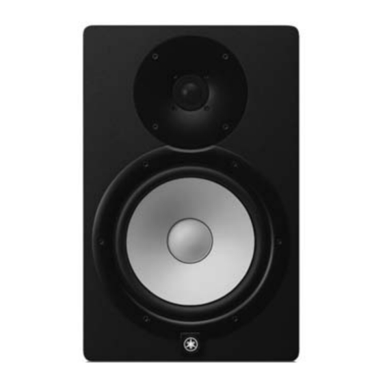
Yamaha Electone HS-8 Manual de serviço
HS8/HS7/HS5
2-2-2 Maximum Output
Measurement condition
Criteria
The following outputs are obtained, total har-
monic distortion is measured.
The signal is input to
the INPUT 1 (XLR).
SPOUT (LF)
Red-Black
The following outputs are obtained, total har-
monic distortion is measured.
The signal is input to
the INPUT 1 (XLR).
SPOUT (HF)
Yellow-Blue
* Measure this inspection within 5 seconds.
2-2-3 Total Harmonic Distortion
Measurement condition
Criteria
The following outputs are obtained, total har-
monic distortion is measured.
The signal is input to
the INPUT 1 (XLR).
SPOUT (LF)
Red-Black
The following outputs are obtained, total har-
monic distortion is measured.
The signal is input to
the INPUT 1 (XLR).
SPOUT (HF)
Yellow-Blue
18
HS8
THD + N =
Min +23.6 dBu
1% or less.
HS7
THD + N =
Min +22.4 dBu
1% or less.
HS5
THD + N =
Min +20.0 dBu
1% or less.
HS8
THD + N =
Min +26.1 dBu
1% or less.
HS7
THD + N =
Min +25.1 dBu
1% or less.
HS5
THD + N =
Min +23.3 dBu
1% or less.
HS8
THD + N =
+21.0 ± 0.2 dBu
0.2% or less.
HS7
THD + N =
+20.1 ± 0.2 dBu
0.2% or less.
HS5
THD + N =
+18.8 ± 0.2 dBu
0.2% or less.
HS8
THD + N =
+21.8 ± 0.2 dBu
0.2% or less.
HS7
THD + N =
+20.7 ± 0.2 dBu
0.2% or less.
HS5
THD + N =
+19.3 ± 0.2 dBu
0.2% or less.
2-2-4 Frequency Response
Measurement condition
The signal of -20dBu is input to
INPUT 1(XLR), and the output
voltage is measured.
The signal of -10dBu is input to
INPUT 1(XLR), and the output
voltage is measured.
1.7kHz
-20dBu
47.0Hz
-20dBu
1.8kHz
-20dBu
51.0Hz
-20dBu
Each signal is
input to INPUT
1.7kHz
1(XLR), and the
-20dBu
output voltage is
measured.
65.0Hz
-20dBu
2.9kHz
-10dBu
2.7kHz
-10dBu
3.1kHz
-10 dBu
Criteria
A1
SPOUT(LF)
A2
Red-Black
A3
A4
SPOUT(HF)
A5
Yellow-Blue
A6
T h e r a n g e
of -3.0±2dB
based on A1.
The range of
+ 9 . 9 ± 2 d B
based on A1.
T h e r a n g e
of -3.0±2dB
based on A2.
SPOUT(LF)
Red-Black
The range of
+ 5 . 8 ± 2 d B
based on A2.
The range of
-3±2dB based
on A3.
The range of
+ 4 . 5 ± 2 d B
based on A3.
T h e r a n g e
of -3.0±2dB
based on A4.
T h e r a n g e
SPOUT(HF)
of -3.0±2dB
Yellow-Blue
based on A5.
T h e r a n g e
of -3.0±2dB
based on A6.