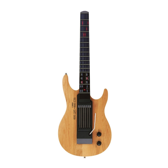
Yamaha EZ-EG 서비스 매뉴얼 - 페이지 9
{카테고리_이름} Yamaha EZ-EG에 대한 서비스 매뉴얼을 온라인으로 검색하거나 PDF를 다운로드하세요. Yamaha EZ-EG 34 페이지. Song chord chart
Yamaha EZ-EG에 대해서도 마찬가지입니다: 소유자 매뉴얼 (2 페이지), 짧은 설명서 (2 페이지), 보충 설명서 (3 페이지)

8.
PN Circuit Board, Key Top Rubber
(Time required: about 8 minutes)
8-1
Remove the lower case assembly. (See procedure 1.)
8-2
Remove the three (3) screws marked [N100]. The earth plate
can then be removed. (Fig. 10)
8-3
Remove the four (4) screws marked [80]. The fingerboard
can then be removed. (Fig. 10, 11)
Body assembly
Body assembly
Body assembly
[80]
[80]
[80]:
Bind Head Tapping Screw-P 4.0X35 MFZN2BL (V8525500)
[N100]: Flat Head Tapping Screw-P 3.0X16 MFZN2BL (VE009200)
LSI PIN DESCRIPTION
MN101C027YB (XS711200) CPU
PIN
NAME
I/O
NO.
1
S1
I
2
S2
I
3
S3
I
Switch matrix data
4
S4
I
5
S5
I
6
VREF+
-
Power supply (+5V, analog)
7
VDD
-
Power supply (+5V)
8
OSC2
O
Crystal oscillator (8MHz)
9
OSC1
I
Crystal oscillator (8MHz)
10
VSS
-
Ground
11
XI
I
Not used
12
XO
O
Not used
13
MMOD
I
Memory mode select (Grounded)
14
RD0
O
Rotary encoder data
15
RXD
I
MIDI receive data
16
D0
O
17
D1
O
18
D2
O
LED and switch drive data
19
D3
O
20
D4
O
21
/RST
I
Reset
22
D5
O
23
D6
O
24
D7
O
LED and switch drive data
25
D8
O
26
D9
O
27
S6
I
28
S7
I
29
S8
I
Switch matrix data
30
S9
I
31
S10
I
32
S11
I
[N100]
[N100]
[N100]
Earth plate
Earth plate
Earth plate
Neck assembly (Neck)
Neck assembly (Neck)
Neck assembly (Neck)
(Fig. 10)
FUNCTION
*
The neck is attached to the body. It cannot be removed.
8-4
Remove the two (2) screws marked [N70] from the finger-
board. The PN circuit board and key top rubber can then be
removed. (Fig. 11)
Fingerboard
Fingerboard
Fingerboard
[N70]
[N70]
[N70]
[N70]: Bind Head Tapping Screw-P 3.0X6 MFZN2BL (EP630220)
PIN
NAME
I/O
NO.
33
S12
I
34
S13
I
Switch matrix data
35
S14
I
36
TXD
O
MIDI transmit data
37
S15
I
38
S16
I
Switch matrix data
39
S17
I
40
S18
I
41
L16
O
42
L17
O
43
L18
O
44
L19
O
45
L8
O
46
L9
O
LED drive data
47
L10
O
48
L11
O
49
L12
O
50
L13
O
51
L14
O
52
L15
O
53
L7
O
54
L6
O
55
L5
O
56
L4
O
LED and switch drive data
57
L3
O
58
L2
O
59
L1
O
60
L0
O
61
VREF
-
Grounded
62
AD0
I
Analog input
63
AD1
I
Analog input
64
S0
I
Switch matrix data
[N70]
[N70]
[N70]
PN
Key top rubber
Key top rubber
Key top rubber
(Fig. 11)
PN: IC001
FUNCTION
EZ-EG
9
