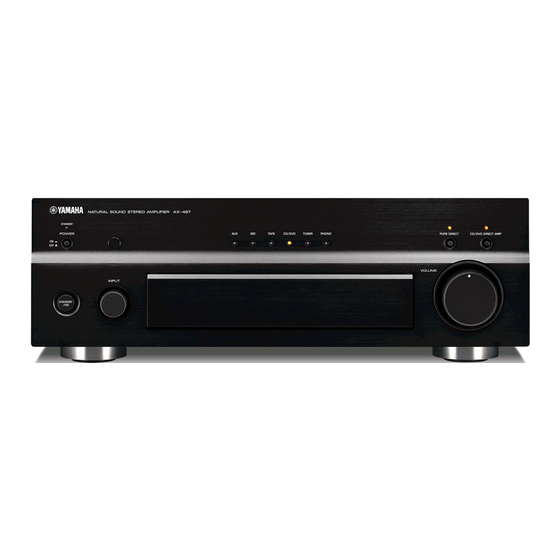
Yamaha AX-497 서비스 매뉴얼 - 페이지 9
{카테고리_이름} Yamaha AX-497에 대한 서비스 매뉴얼을 온라인으로 검색하거나 PDF를 다운로드하세요. Yamaha AX-497 36 페이지. Stereo amplifier
Yamaha AX-497에 대해서도 마찬가지입니다: 소유자 매뉴얼 (23 페이지), 소유자 매뉴얼 (24 페이지)

- 1. Table of Contents
- 2. Important Notice
- 3. To Service Personnel
- 4. Impedance Selector
- 5. Remote Control Panel
- 6. Front Panel
- 7. Rear Panels
- 8. Specifications
- 9. Internal View
- 10. Disassembly Procedures
- 11. Adjustment
- 12. IC Data / Block Diagram
- 13. Pin Connection Diagram / Printed Circuit Board
- 14. Parts List
- 15. Exploded View
- 16. Remote Control Rax15
QQ
3 7 63 1515 0
DISASSEMBLY PROCEDURES
• Remove parts in disassembly order as numbered.
• Disconnect the power cable from the AC outlet.
1. Removal of Top Cover
a. Remove 4 screws (
e
). (Fig. 1)
b. Slide the Top Cover rearward to remove it. (Fig. 1)
2. Removal of Front Panel Unit
a. Remove the INPUT knob.
b. Remove 1 screw (
Top. (Fig. 1)
c. Remove 7 screws (
Panel Unit. (Fig. 1)
3. Removal of Plate Side
Remove 2 push rivets (
Side L/R. (Fig. 1)
4. Removal of Sub Chassis Unit
a. Remove 1 push rivet (
b. Remove 2 screws (
Unit forward. (Fig. 1)
c. Loosen the harness fixture fixing the cable.
d. Remove connectors CB221, CB226, CB302, CB306,
TE
L 13942296513
CB532, CB581 and CB681 and then remove the Sub
Chassis Unit. (Fig. 1)
t
t
www
.
http://www.xiaoyu163.com
q
w
), 1 screw (
) and 4 screws (
r
) and then remove the Support
t
) and then remove the Front
y
) and then remove the Plate
u
). (Fig. 1)
i
) and then slide the Sub Chassis
i
r
i
x
ao
y
i
http://www.xiaoyu163.com
8
q
r
t
y
u
i
Q Q
3
6 7
1 3
q
w
u
y
u163
.
Fig. 1
2 9
9 4
2 8
w
e
1 5
0 5
8
2 9
9 4
e
e
q
m
co
y
AX-497
9 9
2 8
9 9
9
