Clarke CEB102 운영 및 유지 관리 지침 - 페이지 4
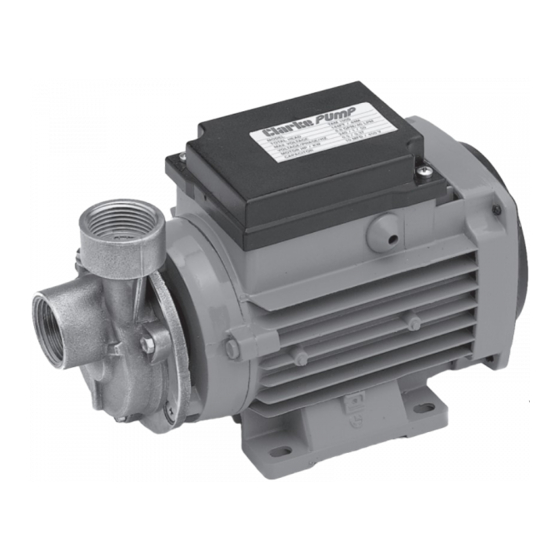
{카테고리_이름} Clarke CEB102에 대한 운영 및 유지 관리 지침을 온라인으로 검색하거나 PDF를 다운로드하세요. Clarke CEB102 4 페이지. Non-submersible water pump

WATER CONNECTIONS
IMPORTANT: The pump must not be connected to the power supply until the hose/
pipe installation is completed.
If any part of the system is to be connected to the mains water supply, do ensure
that you comply with your local water authority regulations.
Because of the variety of possible installations, no plumbing accessories are supplied
as standard with your pump. However, accessories designed specifically for this
range of pumps are available from your CLARKE dealer and are listed on page 7.
The pump must always be installed and operated in a horizontal position i.e. with
the outlet port facing vertically upwards. The fixing holes in the base should be
used as necessary to secure the pump firmly in its operating position. Also, ensure
that there is adequate air circulation around the motor.
Avoid situations where there is the risk of water coming into contact with the
outside of the pump. Neither the motor or the terminal box are intended to be
waterproof.
These notes are for guidance on how to achieve a proper working system.
The schematic diagrams illustrate possible methods of pipework installation. Water
intake can be by means of either:- A. Gravity Feed or B. Suction Lift.
Water being taken in by the pump should,
whenever possible, be fed by means of
gravity (Method A). However, if this is not
possible then water may be drawn from a
lower level by means of suction (Method B).
The suction lift i.e. the vertical distance
between the water level and the pump
should not exceed distance specified for your
pump (see Specifications on page 7).
When using this method, a foot valve, must be fitted to the lower
end of the suction hose, (as illustrated), so as to help retain water
in the suction system.
The delivery head i.e. the vertical distance between the pump
and the point of discharge should be at least 5 feet. If this cannot
be achieved naturally, then it can be simulated by restricting the
outlet flow from the pump.
The illustration shows a gate valve (V) installed in-line on the
delivery side of the pump which can be set as required to regulate
the flow of water.
Do not place any such restriction on the suction side of the pump unless it serves
only to isolate a gravity fed water supply.
To prevent unnecessary strain or possible distortion to the pump, ensure that
adequate support is provided to the hoses and/or pipes. Remember they will be
considerably heavier when filled with water.
A - Gravity Feed
To Pump
Isolating Valve
Filter Foot
Valve
4
Should sand, chemical or other
contaminant come into contact with the
pump, flush through with cold clean
water as soon as possible.
Protect the pump and pipework from
freezing. The formation of ice may cause
serious damage.
PRIMING
When suction lift is used to draw water into
the pump it is essential that all connections
and hoses are completely air tight,
otherwise the system will not work.
Before pumping will start it is necessary
to completely fill the suction side with
water. This is known as priming the pump and is carried out as follows :-
1
.
With the pump, all pipes/hoses and the foot valve in position, unscrew the
priming plug (small hexagon nut on top of pump body, adjacent to the pump
outlet) and fill to capacity with clean water. Replace the priming plug.
NOTE: As the filler hole is quite small, it is recommended that you fill the inlet pipe with water
before it is connected to the pump, and top up through the filler plug once the pipe is
connected.
2.
Adjust any device which may be fitted to the outlet side of the pump, so as to
ensure as great a flow as possible.
3.
Switch on the pump. Water should start to flow through the system. Check for
leaks and adjust the flow if necessary using the gate valve (or other type of
restriction) on the delivery side of the pump. Remember that some resistance
(head) is required on the outlet side of the pump to prevent motor overload.
TROUBLE SHOOTING
If the system is set up properly, there is little likelihood of problems arising, but if
water will not flow as it should then check the following points:-
1.
The suction hose and connections including the filler plug need to be
completely air tight, otherwise air will be drawn in and either reduce or
completely stop the flow of water.
2.
Ensure that the system has been fully primed with water up to the level of the
filler plug.
3.
Check to see that no foreign matter is fouling the intake system and check
the filter is not blocked or obstructed.
4.
Check that the vertical height between the level of the water intake and the
ultimate discharge point does not exceed 38 metres. If this should be the
case then the height must be reduced.
Should you still experience problems, then contact your Clarke dealer, or CLARKE
International Service Department for advice.
B - Suction lift
Outlet Restricter
Valve
V
Outlet Port
Inlet Port
From Supply
5
