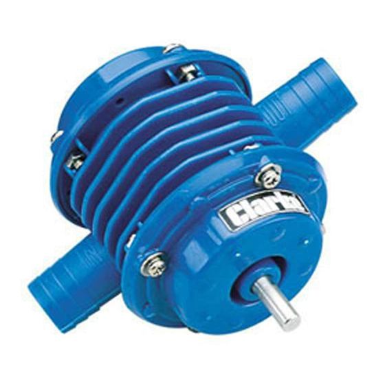
Clarke CPP3000B 매뉴얼 - 페이지 2
{카테고리_이름} Clarke CPP3000B에 대한 매뉴얼을 온라인으로 검색하거나 PDF를 다운로드하세요. Clarke CPP3000B 2 페이지. Drill-powered pump

Instructions for use
1. Attach suitable 3/4" dia hose to the inlet and
outlet ports using worm drive clips, (not
supplied), ensuring they are completely air
tight. The inlet port is marked 'IN' and the outlet
port 'OUT'.The inlet hose be completely sound
with no pin holes. Test it prior to use by
blocking off one end and blowing into it.
Always attach the filter (provided), to the foot of
the hose, as shown in the diagram. Use a
suitable adhesive (not supplied) to ensure it is
firmly and permanently attached.
2. Install the pump in the chuck of a suitable drill,
with the drill disconnected from the mains
supply.
NOTE: While the pump can be held by hand
during fairly short periods of operation, for extra
stability it is advised that the pump be attached to
'U' bolt
drill
a board using the 'U' bolt supplied, as shown in
the diagram. If necessary weigh the board down
or secure it in some way to prevent it from
moving during operation.
When securing the pump to a board, ensure the
pump and drill remain perfectly in line. Do not
under any circumstances tighten down the 'U'
bolt in such a way as to cause the pump and drill
to become 'bowed'. The drill should be free to
move but have its weight supported, keeping it
perfectly in line with the pump.
3. Insert the inlet hose into the liquid with the
pump as near to it as possible bearing in mind
that the maximum lifting height is 2 metres.
Parts & Service: 020 8988 7400/E-mail:[email protected] or [email protected]
Ensure also that the outlet hose is led away to
a suitable place of discharge. If a long hose is
used, ensure that there is no likelihood of it
becoming damaged or blocked by vehicles or
other means. The maximum height to which
the pump will deliver water is 15 metres.
4. When installation is complete, plug the drill into
the mains supply and switch on.
NOTE: If the pump does not prime and begin to
deliver liquid within 10 seconds, switch off and
investigate the cause.
The most common cause is leaks on the inlet side
of the pump, is where air is being drawn in through
a damaged or insecure hose.
Other causes are - blocked inlet or outlet pipes,
trying to draw from too great a height (2M max.),
or deliver to too great a height (15M max.), drill
power too low, or worn pump seals.
WARNING:
not be restricted in any way either during or prior
to use'.
Do not connect the outlet of this pump to a system
that restricts its flow or has a head height greater
than 1.5 metres.
Maintenance
To prolong the life of the pump, always flush
thoroughly with a water/detergent solution and
then with water only. Finally, apply a few drops of
light lubricating oil into the inlet port, rotating the
worm drive
drive shaft by hand as you do so.
clip
Store in a dry cool location. Do not leave exposed
to the elements.
Four vane seals, together with an end plate 'O'
Ring and a shaft seal, are provided should the
pump require servicing.
board
To replace the vane seals, remove the four
screws securing the end cover, - at the SHAFT
end of the pump, and withdraw the shaft complete
with vanes from the pump body.
Pull out the vane seals and replace with new
ones.
Renew the large 'O' ring on the inside face of the
end cover and apply silicon grease to the vanes,
ensuring they are perfectly free to move, before
reassembly.
Before fitting the four end cover screws, twist the
end plate whilst applying gentle pressure, to
ensure the locating dowels seat correctly.
Tighten the four end cover screws progressively,
taking care not to vertighten them as this could
distort the body of the pump and cause severe
damage, possibly rendering the pump inoperable.
'The outlet flow from this pump must
