CAME A 5024 N 설치 매뉴얼 - 페이지 4
{카테고리_이름} CAME A 5024 N에 대한 설치 매뉴얼을 온라인으로 검색하거나 PDF를 다운로드하세요. CAME A 5024 N 13 페이지. Ati series
CAME A 5024 N에 대해서도 마찬가지입니다: 설치 매뉴얼 (13 페이지)
5.2 Tools and materials
Make sure you have all the tools and materials you will need for the installation at hand to work in total safety and compliance
with the current standards and regulations. The following figure illustrates the minimum equipment needed by the installer.
5.3 Cable list and minimum thickness
Connections
Control panel power supply 230V 2F
Flashing light 24V
Photocell transmitters
Photocell receivers
24V Accessories power supply
Command buttons
Endstop
Encoder plug
Antenna connection
N.B.: If the cable length differs from that specifi ed in the table, then you must determine the proper cable diameter in the basis of the
actual power draw by the connected devices and depending on the standards specifi ed in CEI EN 60204-1.
For connections that require several, sequential loads, the sizes given on the table must be re-evaluated based on actual power draw
and distances.
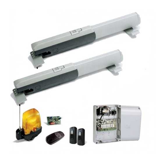
5.4 Standard installation
7
2
3
4
4
Type of cable
Length of cable 1 < 10 m
3G x 1,5 mm
2 x 0,5 mm
FROR CEI
2 x 0,5 mm
20-22
4 x 0,5 mm
CEI EN
2 x 0,5 mm
50267-2-1
2 x 0,5 mm
3 x 0,5 mm
2402C 22AWG
RG58
4
6
1
8
1) Operator
2) Control panel
3) Radio receiver
4) Photocells
Leng. cable 10 < 20 m
2
3G x 2,5 mm
2
2
2 x 1 mm
2
2 x 0.5 mm
2
4 x 0,5 mm
2
2 x 0,5 mm
2
2 x 0,5 mm
2
2
3 x 1 mm
max. 30 m
max. 50 m
4
5) Selector switch
6) Antenna
7) Flashing light
8) Transmitter
Leng. cable 20 < 30 m
2
2
3G x 4 mm
2
2 x 1,5 mm
2
2
2 x 0,5 mm
2
2
4 x 0,5 mm
2
2
2 x 1 mm
2
2
2 x 0,5 mm
2
3 x 1,5 mm
4
5
1