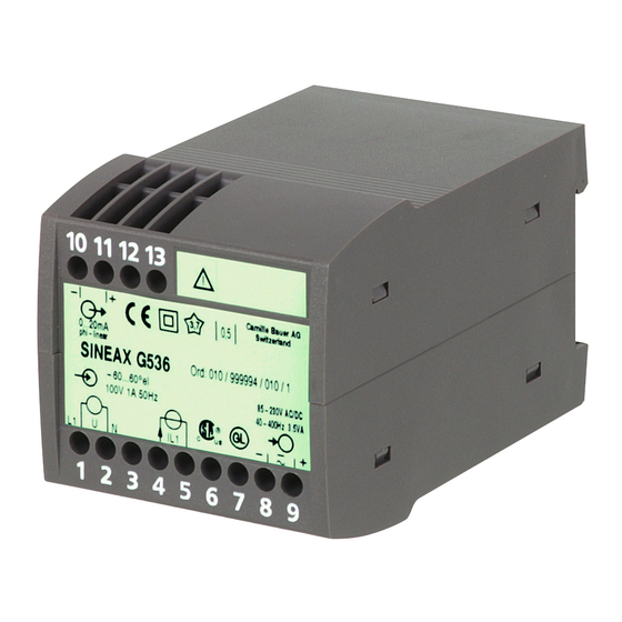
Camille Bauer SINEAX G536 사용 설명서 - 페이지 12
{카테고리_이름} Camille Bauer SINEAX G536에 대한 사용 설명서을 온라인으로 검색하거나 PDF를 다운로드하세요. Camille Bauer SINEAX G536 17 페이지. Transducer for phase angle or power factor
Camille Bauer SINEAX G536에 대해서도 마찬가지입니다: 사용 설명서 (16 페이지)

Accuracy (acc. to IEC 688)
Reference value:
Output span
Basic accuracy:
Class 0.5
Safety
Pollution degree:
2
Installation category:
III
Environmental conditions
Operating temperature: – 10 to + 55 °C
Storage temperature:
– 40 to + 70 °C
Relative humidity:
≤ 75%, no dew
Altitude:
2000 m max.
Indoor use statement
4. Mounting
The SINEAX G536 can be mounted on a top-hat rail.
Note "Environmental conditions" in Section
"3. Technical data" when determining the place of
installation!
Simply clip the device onto the top-hat rail (EN 50 022) (see
Fig. 1).
Fig. 1. Mounting onto top-hat rail 35 × 15 or 35 × 7.5 mm.
5. Electrical connections
Connect the electric conductors acc. to the instructions on
type label.
Make sure that all input cables are not live (po-
tential-free) when making the connections!
Impending danger by high input voltage or
high power supply voltage!
Be aware of danger by open circuit current
transformer!
12
Also note that, ...
... the data required to carry out the prescribed
measurement must correspond to those marked on
the nameplate of the SINEAX G536 (
input,
measuring output and
supply, see Fig. 5)!
... the resistance in the output circuit may not over-
range the current output value
15 V
R
max. [kΩ] ≤
ext
I
AN
(I
= current output value)
AN
and not underrange the voltage output value
U
AN
R
min. [kΩ] ≥
ext
4 mA
(U
= voltage output value)!
AN
... the measurement output cables should be twisted
pairs and run as far as possible away from heavy
current cables!
In all other respects, observe all local regulations when
selecting the type of electrical cable and installing them!
– +
10
11
12 13
1
2
3
4 5
6
7
8
9
–
U
I
Fig. 2. Power supply to termi-
nals 8 and 9.
– +
–
10
11
12 13
1
2
3
4 5
6
7
8
9
U
I
Fig. 4. Power supply connected to the low tension to terminals
12 and 13.
measuring
power
– 12 V
resp. ≤
[mA]
– I
[mA]
AN
[V]
– +
10
11
12 13
1
2
3
4 5
6
7
8
9
U
I
Fig. 3. Power supply internal
from measuring input, power
supply not required.
= Measuring input
= Measuring output
= Power supply
