3M 710 사용 설명서 - 페이지 8
{카테고리_이름} 3M 710에 대한 사용 설명서을 온라인으로 검색하거나 PDF를 다운로드하세요. 3M 710 20 페이지. Splicing rig
3M 710에 대해서도 마찬가지입니다: 브로셔 및 사양 (4 페이지), 사양 (4 페이지)

3.9 Wrap the group to be spliced with the other group
holder. Dress the pairs into the module body over
the colored peaks with the conductor ends exiting
towards the color code guide. Do not pull the
conductors tight to the back of the connector. Use
the error tester tool to check for correct conductor
placement.
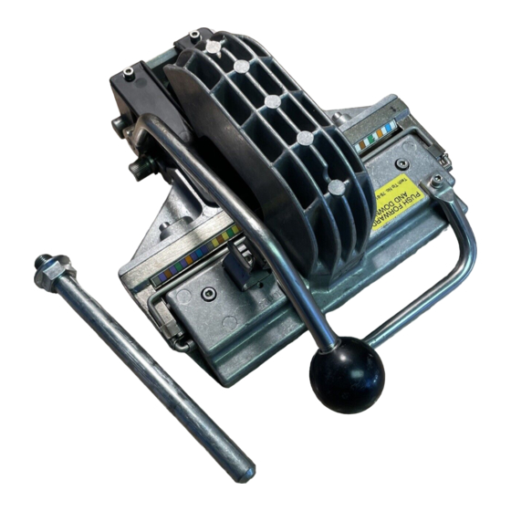
3.10 Spread the conductors around the "T" bar without
disturbing them in the module body. Pull the "T" bar
up above the module body. Push the "T" bar forward
and down until contact is made with the conductors.
Pull the handle down to the stop, seating and cutting
the conductors in the module body. Remove the
excess conductors. Engage the handle into the
retaining clip, pull the "T" bar up, and place into the
open position.
3.11 Place a cap on the module body. Use finger pressure
to push down the cap to pre-engage it to the module
body. The cap latches should face the color code
guide. Pull the "T" bar up above the cap. Push the
"T" bar forward and down until contact is made with
the cap. Pull the handle down to the stop, seating the
cap into the module body. Engage the handle into the
retaining clip, pull the "T" bar up, and place into the
open position.
3.12 Push in the "L" clip to release the module and
remove from the splicing rig. The 25-pair straight
splice module is complete.
8
78-815-304--E
