Cypress PowerSoC CY3267 빠른 시작 매뉴얼 - 페이지 5
{카테고리_이름} Cypress PowerSoC CY3267에 대한 빠른 시작 매뉴얼을 온라인으로 검색하거나 PDF를 다운로드하세요. Cypress PowerSoC CY3267 12 페이지. Lighting evaluation kit
3. Out-of-the-Box Setup
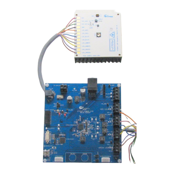
3.1 Connect the LED Daughter Board to the Main Board
The Main Board has screw terminals marked for each of the four output channels and
are labeled RED, GREEN, BLUE, or AMBER. The LED Daughter board provides a
pair of wires for each of the four LEDs to connect to the corresponding connectors on
the Main Board. The wire from the positive terminal of the LED (from the LED Daugh-
ter Board) hooks up to the terminal marked + on the Main Board. The wire from the
negative terminal of the LED (from the LED Daughter Board) hooks up to the terminal
marked BCK or BST on the Main Board.
Table 1 on page 6
describes the wiring
scheme to connect the LED daughter board to the Main Board. This is also shown in
Figure 2
and
Figure 3 on page
6.
The LED Daughter Board also provides four wires to connect to the LM75 temperature
sensor (I2C Data, I2C Clock, VDD, and GND). You can add temperature compensa-
tion to the PowerPSoC Firmware to use these inputs.
Figure 2 LED Daughter Board
Page 5