Cloud CDI-S100 설치 및 설정 매뉴얼 - 페이지 5
{카테고리_이름} Cloud CDI-S100에 대한 설치 및 설정 매뉴얼을 온라인으로 검색하거나 PDF를 다운로드하세요. Cloud CDI-S100 11 페이지. Interface card
Cloud CDI-S100에 대해서도 마찬가지입니다: 설치 매뉴얼 (12 페이지)
CDI-S100 Serial Interface Card
CLOUD ELECTRONICS LIMITED
3
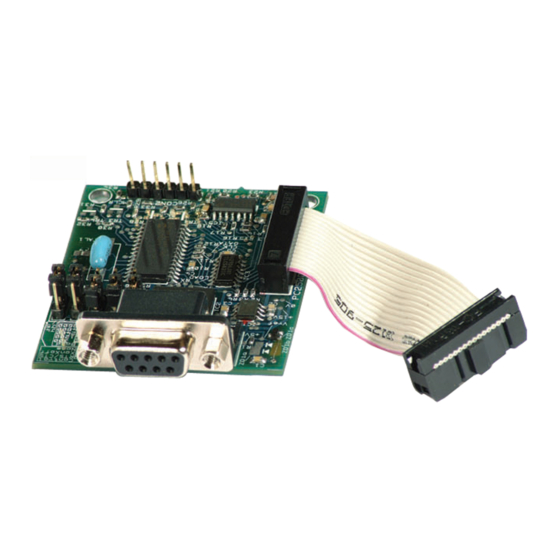
CDI-S100 Configuration
The CDI-S100 has several modes of operation, configurable through a series of jumpers located on the
module itself. The settings of these jumpers are clearly marked on the board itself, with a more detailed
description of each set in the following paragraphs. Settings for the module should be configured to
match the controlling equipment capabilities. In the factory default mode, the module should be capable
of working satisfactorily without further configuration. The module should only be reconfigured if there
are communications problems between the controller and the module.
The CDI-S100 uses a serial data packet consisting of one start bit, eight data bits and one stop bit. The
CDI-S100 does not support parity, so the controlling device should be configured to operate without parity
checking.
3.1 Baud Rate
Setting jumpers J1-3 on the module can alter the speed at which the CDI-S100 processes and receives
information. The available settings for this are:
Baud Rate
300
1200
2400
4800
9600
Table of jumper settings for J1-3
The factory default is for the CDI-S100 to be set to a baud rate of 9600 bits-per-second.
3.2 Flow Control
Setting jumpers J4 and J5 on the CDI-S100 changes the communications mode between hardware
handshaking, software handshaking and no handshaking modes.
Hardware handshaking utilises the two dedicated lines Clear-To-Send (CTS) and Request-To-Send
(RTS) on the 9-pin sub-D connector. The controller uses the RTS line to indicate that there is some data
to be sent. The module then uses the CTS line to indicate that it is ready to receive the data.
In software handshaking mode, the CDI-S100 will send two specific bytes to the controlling terminal. The
system used for this is called Xon/Xoff where X represents transmitter, so an Xoff signal is sent when the
data flow should pause, and a Xon signal is sent for the data flow to resume. The Xon byte, 0x11, is
equivalent to ctrl-Q in ASCII encoding: DC1. The Xoff byte, 0x13, is equivalent to ctrl-S in ASCII
encoding: DC3.
No handshaking mode means the module uses neither of the two aforementioned methods to indicate
readiness. This is the factory default setting since in most systems, the module will be ready to receive
data constantly and will not need to indicate readiness to the terminal.
Mode
No handshaking Low
Xon/Xoff
RTS/CTS
Table of jumper settings for J4 and J5
Setup And Installation Guide
J1
J2
Low
High
High
Low
High
Low
High
High
High
High
J4
J5
Low
Low
High
High
Low
J3
High
Low
High
Low
High
2