Cypress CPT-386 운영 매뉴얼 - 페이지 5
{카테고리_이름} Cypress CPT-386에 대한 운영 매뉴얼을 온라인으로 검색하거나 PDF를 다운로드하세요. Cypress CPT-386 8 페이지. Pc to component scan converter

3. Hardware Description
The following sections describe the hardware components.
3.1. Top Panel
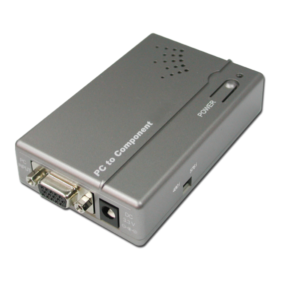
PC to Component
1 Power switch and LED Indicator: When power is turned on the LED will
illuminate in green color. When press power switch once to turn the system
in standby mode and the LED will illuminate in red color.
Note: The factory setting is in power on mode.
3.2. Front Panel
PC
INPUT
1
1 PC Input: Connect the PC input port to the output port of your computer
(desktop, notebook/laptop, or device providing PC resolution output),
using D-Sub 15-pin cable.
2 Power Supply: Plug the 3.3V DC 1A power supply into the unit and connect
the adaptor to AC wall outlet.
3 Component Output: Connect the component output port to the input port
of your display, using 3 RCA cable.
POWER
1
DC
3.3 V
2
3.3. Rear Panel
Cr
OUTPUT
2
Cb
Y
3
