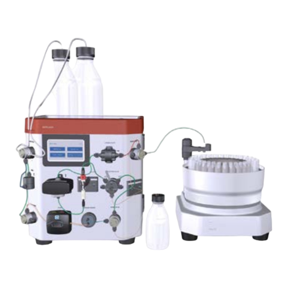
cytiva AKTA start 유지 관리 카드 - 페이지 8
{카테고리_이름} cytiva AKTA start에 대한 유지 관리 카드을 온라인으로 검색하거나 PDF를 다운로드하세요. cytiva AKTA start 14 페이지.

Note: We recommend to keep the instrument On to avoid
condensation in a cold room.
For more details on the procedure for turn on/off the UV
LED, refer to ÄKTA start Operating Instructions.
Note: Make sure that the UV flow cell is assembled tightly,
and the inlet and outlet tubes are fitted tightly to the UV
Monitor. No stray light should enter the UV Monitor.
Instruction
1. Immerse the buffer inlet tubing in DM water.
2. Flush the UV flow cell with DM water using
Pump. Make sure that there are no air bubbles in
the UV flow cell.
3. In the Settings and service screen, tap UV to
access the UV Monitor options.
4. In the UV screen, tap UV LED calibration.
5. Set the Light strength value to 500.
6. Tap Calibrate. A confirmation screen opens.
Select OK to automatically search the Light
strength value to get a minimum Signal
response of 2700 mV.
7. If the Signal value is above 2700 mV, tap Save.
If Signal is below 2700 mV use the arrows to
increase the Light strength until the Signal is
above 2700 mV.
Calibrate the Conductivity Monitor
Temperature sensor calibration
Instruction
1. Place a precision thermometer in the flow path
directly after the Conductivity cell and pump DM
water through system with a flow rate of 0.5 ml/
min.
2. Access Conductivity > Advanced calibration.
3. Note the temperature and type it into the Set
actual temp field, then tap Calibrate.
Sine generator calibration
Instruction
1. Use Manual run to empty the conductivity flow
path.
2. Disconnect the flow cell and dry it with a stream
of air.
3. Access Conductivity > Advanced calibration.
4. Tap Calibrate sine gen. The cell resistance
value should be 60 Mohms.
8
Conductivity flow cell calibration
Prerequisites
Calibration solution: 1.0 M NaCl or 100 mS/cm
conductivity standard solution.
Instruction
1. Fill the flow cell with conductivity standard
solution.
2. Access Conductivity > Calibration.
3. Note the current temperature of the calibration
solution in the conductivity flow cell as displayed
in the Cell temperature field.
4. In the Calibration screen, enter the conductivity
value at current temperature in the Set
conductivity field and then tap Calibrate.
Note:
For conductivity standard solutions, use the supplied
theoretical conductivity value at the current
temperature.
For 1.0 M NaCl calibration solution, read the conductivity
value at the current temperature from the graph
provided in the ÄKTA start Maintenance Manual.
Reference temperature setting
Instruction
1. Access Conductivity > Configuration.
2. Set the Set ref temp value to the temperature
shown in the Conductivity > Calibration
screen.
3. Tap Save.
Note:
The Cell constant value is set automatically when
calibration is performed. Do not change this value.
System performance test
System performance test is performed to make
sure the system is performing within acceptable
limits. It is recommended to run this method during
installation of the instrument or after replacement
of modules such as Pump, UV, Conductivity or
Valves. For a detailed description of the test, refer to
ÄKTA start Operating Instructions.
Required solutions
•
Buffer A: DM water
•
Buffer B: 1.0% Acetone, 1.0 M NaCl
•
Sample: 1.0% Acetone, 1.0 M NaCl (Buffer B)
ÄKTA start Maintenance Cue Card, 29024043 AF
