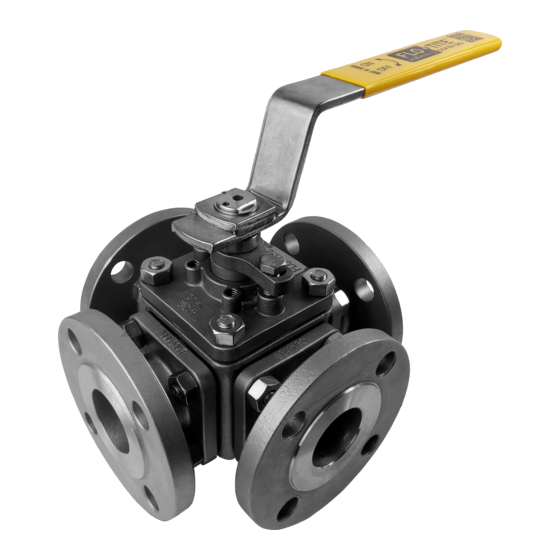
Flo-Tite MPF15 Installation Operation & Maintenance
Browse online or download pdf Installation Operation & Maintenance for Control Unit Flo-Tite MPF15. Flo-Tite MPF15 4 pages. 3-way ball valves

DESIGN:
Central body design, three-fl anged end piece construction, allows ease of maintenance, without special tools. This type
of valve utilizes a true trunnion ball principle. The ball is fi xed, it is not free to move with line pressure. This particular
feature allows tight shut-off to fl ow in either direction or dead ended, regardless of the position of the valve in-line.
1. ON-SITE INSTALLATION
The valve may be fi tted to any position on the pipeline.
Before installation, pipes must be fl ushed clean of dirt and debris that could result in damage to hard or soft parts of the valve.
Piping must be supported so as not to add undue stress to the valve.
2. USE
Maximum results and long life of valves can be maintained under normal working conditions and in accordance with
proper pressure/temperature and corrosion data.
3. MANUAL OPERATIONS
The manual operation for the proper fl ow plan is done by turning the handle a 1/4 turn (90 degree turn).
Visual indication of position is done by visual inspection of the markings on the top of the stem.
4. AUTOMATED OPERATIONS
Valves with actuators should be checked for actuator/valve alignment. Angular or linear mis-alignment will result in high
operational torque and premature packing failure.
5. DISASSEMBLY & CLEANING PROCEDURES
If the valve has been used to control hazardous media, it must be decontaminated before disasembly. It is
recommended that the following steps are taken for safe removal and reassembly.
1. Relieve the line pressure
2. Place valve in half-open position and fl ush the line to remove any hazardous material from valve
3. All persons involved in the removal and disassembly of the valve should wear the proper protective clothing, such as face
shield, glove, apron and etc.
Valves come shipped from the factory containing a lubricant. This is for break-in and may be removed if it is objectionable to
a particular application by disassembly and cleaning with a proper solvent.
6. DISASSEMBLY FOR STEM AND SEAL REMOVAL
(CAUTION: Ball valves can trap fl uids in ball cavity when closed)
Stem seal leakage may be corrected without disassembly by tightening the packing gland bolts until such leakage stops.
If the leakage continues or valve operating torque becomes excessive, or the stem seals are worn, replacement will be
necessary.
(Warning: Do not remove the packing gland while line is under pressure! )
Remove fl ange bolts and nuts and lift valve from line for servicing. NOTE: care should be taken to avoid scratching or damag-
ing serrated fl ange faces. Valves can be heavy, they should be adequately supported before removal from the line has begun.
Loosen handle set screw and remove handle and stop plate. Remove gland nuts and packing gland. Mark each fl ange to the
body joint (3 fl anges). Mark top cap to the body joint. This is to allow ease of alignment in reinstallation.
Remove the nuts holding fl anged pieces and top cap for disassembly.
Remove all three end pieces, then the top cap, leaving the ball to last.
Take extreme care when removing ball as not to scratch seating surface or the stem, which will result in leakage after reassem-
bly.
Remove all seats, seals and the thrust bearing.
Note: If the valve is supplied with body cavity fi llers:
Cavity fi ller is supplied in two parts: top and bottom. They are removed after the top cover and end caps are removed. Remove
top half then valve ball, then bottom cavity fi ller.
Installation, Operation & Maintenance
MPF15 3-Way Ball Valves
Page 1
IOM-MPF15-01
