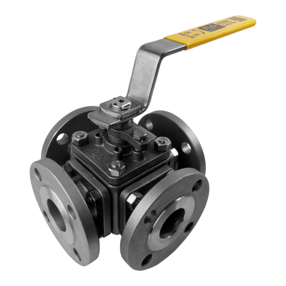
Flo-Tite MPF15 Installation Operation & Maintenance - Page 2
Browse online or download pdf Installation Operation & Maintenance for Control Unit Flo-Tite MPF15. Flo-Tite MPF15 4 pages. 3-way ball valves

7. RECOMMENDED SPARE PARTS
The recommended spare parts for normal service conditions are the "soft" parts contained in the repair kit available from FTI;
stem seals, body seals and seats. For more severe conditions, spare balls and stems may be needed.
8. VISUAL INSPECTION
Clean and inspect metal parts. It is not necessary to replace the ball and stem unless the seating surface have been damaged by
abrasion or corrosion. We strongly recommend of all soft parts whenever the valve is disassembled from reconditioning. This
is the best protection against valve leakage after assembly. Replacement parts can be ordered in kit form. NOTE: the valve
may be assembled and operated dry where no lubricants are allowed in the system; however, a light lubrication of mating
parts will aid in assembly and reduce initial operating torque. Lubricant used must be compatible with intended line content.
9. ASSEMBLY
Install the thrust bearing in the bottom center of the body.
Install the ball in the body, making sure the trunnion of the ball goes into the thrust bearing.
Install the seats in each of the fl anged end pieces with spherical curvature facing the mating ball.
Install the top cap and body gasket making sure to align the marks made during disassembly. Tighten down in a criss-cross
pattern. Keep gap even. This will insure the valve stop or actuator is in the proper position.
Now install the packing and packing gland with packing gland bolts. Tighten bolts evenly.
The installation of the fl anged end pieces must be done in the following way to insure damage.
First install the left and right end pieces with the nuts aligning the marks made during disassembly. This is to insure fl ange-
to-fl ange mating and alignment of the valve bolt holes. Make sure the ball ports are aligned with the end pieces as not to
pinch the seats during tightening. Do not tighten one end piece fully until both ends are installed. Due to the location, the nuts
should be torqued down evenly using a criss-cross pattern and alternating between each end until metal-to-metal contact is
achieved. During this step, check body to end piece gap and keep gap consistent. Uneven tightening may result in pinching of
the seats and subsequent leakage after reassembly.
The installation of the center end piece is done fi rst by rotating the ball until the blind side of the ball is facing area where the
end piece is being installed, aligning previous marks. Tighten the nuts using a criss-cross pattern. Make sure the gap of the
end piece to valve remains consistent metal-to-metal contact is achieved.
Cycling the valve slowly back to the proper fl ow plan by turning the ball slowly insures the seal lips assumes a permanent seal
against the ball. A fast turning motion may not allow proper mating to occur.
Test valve, if at all possible, prior to placing valve back into line.
WARNING: Not properly securing valve may cause it to separate from the pressure source and result in injury. Always join
the valve to the companion fl anges of the same pressure rating as the valve. Use a full set of proper bolts.
Please carefully review all important procedures in this manual. If anything is
not clear, please feel free to contact Flo-Tite directly
Page 2
IOM-MPF15-01
