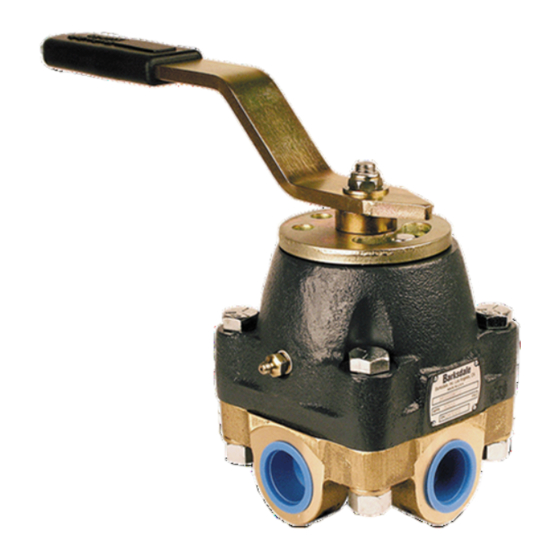
Barksdale 920 Series Installation Instructions Manual - Page 13
Browse online or download pdf Installation Instructions Manual for Control Unit Barksdale 920 Series. Barksdale 920 Series 16 pages. Heavy duty valve

8.2
4-WAY HEAVY DUTY CONTROL VALVE REPAIR
This section outlines the disassembly and reassembly procedures for the 4-way heavy
duty control valves. Differences in reassembling the selector, manipulator, and diverter
type valves are pointed out in the procedures below. In all other steps, various types of
valves and valves of all sizes use the same procedures.
WARNING!
Isolate the 4-way valve from all system pressure before performing any disassembly procedures.
Also, cycle valve handle fully in the clockwise & counter-clockwise position. This will ensure any
remaining static pressure trapped within the valve is bled off.
The numbers in parentheses correspond to the item numbers shown on Figure 1.1 and the parts index shown
on Figure 1.2.
8.3
DISASSEMBLY 4-Way Hydraulic Control Valve
1. Disconnect all fittings from the valve body (3).
2. Move the valve to a clean work area, free of dirt, dust, grit, etc.
3. Remove handle nut (32), shaft washer (31), handle (29), and spacer (28) from the
valve shaft.
4. Remove retainer ring (27) from the shaft, remove detent disc (26), detent ball (24) and detent
spring (23).
5. Turn valve upside down and secure housing (18).
6. Remove the four body nuts (1), lock washers (2) and body bolts (22).
Panel mount versions only: remove four body bolts (22), lock washers (2), and stud panel
standoff (33).
7. Lift body (3) up to remove from housing (18).Ensure Internal components do not fall out.
8. Place valve body (3) on a flat surface so process connections are facing down and remove
pressure seals (8) and washer springs (5) from the from the three cavities.
9. Remove o-ring (7) and backup ring (6) from pressure seal (8)
10. Remove the housing o-ring (16) from valve body (3).
11. Remove sleeve (17) applicable to 3/4", 1", 1 ½" valves only.
12. Remove rotor (9)
13. Remove thrust ball bearing assembly (13) applicable to 3/4", 1", 1 ½" valves only.
a. Remove thrust washer (13) ball bearings (15) applicable to 3/8", 1/2" valves only.
b. Remove thrust washer (13) ball bearings (15) retainer (14) applicable to 1/4" valves only.
Do not strike nut and/or shaft with a metallic hammer as damage to components may
occur.
14. Reinstall handle nut (32) on shaft (10). Using a nonmetallic mallet or a block of wood between
the nut and mallet, drive the shaft (10) sufficiently out of the back of the housing (18).
15. Remove nut (32) and pull shaft (10) completely out of housing (18).
16. Remove o-ring (11,) from shaft.
17. Remove o-ring (12) applicable on 3/4", 1", 1 ½" only
____________________________________ ____________________________________
Barksdale, Inc. 3211 Fruitland Avenue, Los Angeles CA 90058 (800)835-1060 www.barksdale.com Bulletin No. 272350-A, 07-05-13
Buy: www.ValinOnline.com | Phone 844-385-3099 | Email: [email protected]
Caution
13
