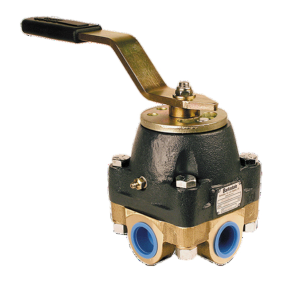
Barksdale 920 Series Installation Instructions Manual - Page 14
Browse online or download pdf Installation Instructions Manual for Control Unit Barksdale 920 Series. Barksdale 920 Series 16 pages. Heavy duty valve

8.4
Cleaning and Inspecting, 4-Way Hydraulic Control Valve
1. Thoroughly clean and inspect the body (3). Pay particular attention to the areas around the three
cavities for signs of washout. If washout in these areas is severe, the entire valve assembly
should be replaced.
2. Clean & Inspect body (3), housing (18) rotor (9), shaft (10) thrust ball bearing set (13) and detent
disc (26). Replace worn or damaged components.
6.4 Reassembly, 4-Way Hydraulic Control Valve
1. Prior to reassembly of the valve, discard the following parts that were removed during
disassembly that will not be replaced:
all pressure seals, O-rings and backup rings
pressure seal spring washers
ball bearings
ball bearing retainer
thrust washers
retainer ring
rotor
2. Install new spring washers (5) into valve body (3)
3. Grease the area around the ports on the body (3).
NOTE: Repair kits provide new O-rings (7) and backup rings (6) pre-installed on pressure seals
(8). If items were purchased separately refer to step 4.
4. Install new o-ring (7) and backup rings (6) on to pressure seals (8) refer to Figure 1.1 for proper
o-ring and backup ring orientation.
5. Using a media compatible grease apply a coat on the o-ring (7) and backup ring (6) pressure
seal (8) and install with the beveled edges facing outward, toward the surface of the rotor.
Repeat for all pressure seals, when complete set body aside.
Do not use any metal object to push the seal ring into the seal container. The seal
rings are manufactured to a very specific tolerance. These tolerances would be
damaged by contact with metal tools. Use fingers, preferably protected with clean
gloves. Avoid contacting the beveled edges of the seal rings directly with the fingers.
The beveled edges of the seal rings are sealing surfaces which will corrode if
contacted by the natural acids on fingers. If it is necessary to push the seal rings in
with the fingers, apply a sufficient coating of oil to the seal rings. The oil acts as a
barrier between the acids and the metal.
6. Install new o-ring (11) shaft (10) applicable to all sizes.
7. Install new o-ring (12) on shaft (10) applicable on 3/4", 1", 1 ½" valves only.
8. Lightly grease the shaft (10)
9. Secure housing (18) upside down and install shaft (10) it into the housing (18).
10. Thoroughly grease the inside of the housing (18).
11. Grease the thrust ball bearing assembly (13) applicable to 3/4", 1", 1 ½" valves only
a. Grease thrust washers (13) ball bearings (15) applicable to 3/8", 1/2" valves only.
b. Grease thrust washer (13) ball bearings (15) retainer (14) applicable to 1/4" valves only.
NOTE: Refer to Figure 1.1 for correct bearing orientations
____________________________________ ____________________________________
Barksdale, Inc. 3211 Fruitland Avenue, Los Angeles CA 90058 (800)835-1060 www.barksdale.com Bulletin No. 272350-A, 07-05-13
Buy: www.ValinOnline.com | Phone 844-385-3099 | Email: [email protected]
Caution
14
