American Time SiteSync IQ Installation And Operation Manual - Page 7

Browse online or download pdf Installation And Operation Manual for Recording Equipment American Time SiteSync IQ. American Time SiteSync IQ 13 pages. Wireless system controller with standard gps & magnetic mount tx antenna
Also for American Time SiteSync IQ: Quick Start Installation Manual (2 pages), Installation And Operation Manual (2 pages), Installation And Operation Manual (7 pages), Installation And Operation Manual (6 pages), Quick Start Installation Manual (2 pages), Quick Start Installation Manual (2 pages), Quick Start Installation Manual (2 pages), Quick Start Installation Manual (2 pages), Quick Start Installation Manual (2 pages), Quick Start Installation Manual (2 pages), Quick Start Manual (2 pages), Quick Start Manual (2 pages), Quick Start Manual (2 pages)
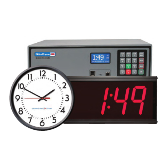
American Time SiteSync IQ Installation And Operation Manual
SiteSync IQ Wireless Controller
Installation Manual

Tone

The audible tone output is located on the left side of the SiteSync IQ Wireless Controller via a RCA style jack (#4). The tone output
is a low level non-amplified signal intended for input to an amplified system.
Tone Selection
Note: Power should be disconnected and off before making any jumper selections.
n
Tone Selection
The Tone card (#5) installed on the SiteSync IQ Wireless Controller provides a menu of eight tones of which four can be selected
to be triggered from the SiteSync IQ System Controller. Place up to four jumper shunts at the lettered positions (see above) that
correspond to the desired tones (use Tone Selection Table above). The tones will be assigned to the trigger terminals in the order
they fall into from A to H where the first tone selected on the way from A to H is assigned to SiteSync IQ System Controller circuit
1, the next tone selected is assigned to circuit 2, and so on. If more than four tones are selected via jumpers, only the first four
(from A to H) are assigned to the SiteSync IQ System Controller circuits 1 through 4. If less than four tones are selected, then only
the circuits needed to correspond to the number of tones will be operational.

Clock

Clock relays are located on the far right side of the block of 14 screw terminals (#14) inside the wiring panel. (See Appendix B for
wiring diagram)
© American Time
Tone Selection Table
A*
512 Hz Steady
B*
Slow Whoop
C*
Siren
D*
Mechanical Bell
E
Klaxon
F
Night Ringer
G
Double Chime
H
Doorbell
*Factory Defaults
Operation
7