Electra Bearcat BC3-L Operating Instructions Manual - Page 2
Browse online or download pdf Operating Instructions Manual for Receiver Electra Bearcat BC3-L. Electra Bearcat BC3-L 12 pages. Fm monitor receiver
Also for Electra Bearcat BC3-L: Operating Instructions Manual (12 pages)

GENERAT DESCRIPTION
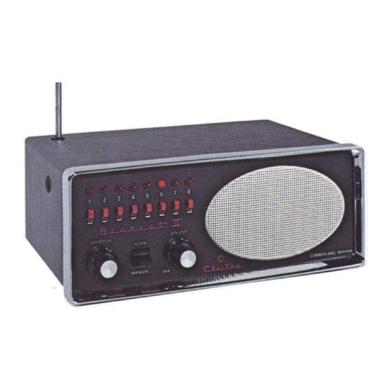
The Bearcat III is a table and motile model, single or dual
band FM monitor rectiver providing automatic scanning of B
channels in one or two of the three Public Safety/Business
Bands at 30-50mHz, L4,6L74mHz and 450-47OmHz-
Its features include: provisions for one or two plug-in
r-f modules; B plug-in crystals in any combination may be
used; high speed automatic or manual scanning; channel
switches to omit scanning of undesired channels; solid state
Iight Emitting Dode channel indicators; comtination squelch
arrd sensitivity control; front-mounted 3" x 5" speaker;
external speaker jack; cables for ll7Yac or l2Vdc operation;
and operation from a singfe tele*oflng
c
oqtjde
antenna.
The most advanced developments in solid state circuitry
are incorporated in this receiver; dud-gate \lOS Field Effect
r-f and mixer transistors provide low ncise and low cro$s-
modulation.
Single conversisr into monolithic guartz crystal
i-f
filters
reduces spurious responses and radiation
and
improves
selectivity;
linear inteEated
circuits
provide i-f
gri;,
detection, audio amplification
and output;
TTL I'C'
multivibrators
and gates provide scanning logic; desired chan-
nels are scanned with
no time lost scanning unwanted
channels.
SPECI FICATIONS
S i z e : 9 " W x 3 5 / B " H x 6 1 i B " D
Weight: 5lbs.
Cabinet: Heavy duty vinyl-clad steel. Non-sliding feet.
P owe r Re q uire me nts : ll7 V a c, l 2 W ; l 3 .B V dc,6 W-
Audio Output:
3 W rms, voice (Power protected at 1.5 W on continuous
tones). External speaker connector provided.
Antenna: Telescoping antenna (supplied). Connector provided for outside
or mobile antenna
Input lmpedance: 50-;0 ohrn-..
Sensitivity:
H and L bands: readable at .25 microvolt for
t
5 kHz
deviation, .7 microvolt for 20 dB signal-to-noise ratio:
U band slightly less'
Channels:
Up to B crystal-controlled channels (in
be scanned iutomatically
or selected individually
Frequency Range:
f,ow band *30-50 mHz, total spread 15 mHz.
High band xl46-L74 mHz, total spread 24 mHz.
UHF band 450-470 mtJLz, total spread 20 mHz-
(*Factory-supplied alignment f9t [,ott band is 3348 mFrz. High band is
supplied'with' 150-f74 mHz alignment. Other alignments are available on
special request.)
Scan Rate: Approximately 25 channels per second.
Crystals: Miniature plug-in type HC-25/U for easy user installation.
Accessories Supplied: All-band telescoping antenna / Universal mo^bile mount-
ing bracket I iI7
Vac power cable / t3.g Vdg pgwe_t_9ahl_e-(Connects
to
"ficcessorv" or "Radio" ?use block. FOR USE WITH NEGATIVE GROUND
SYSTEMS ONLY).
Front Panel Features: Squelch control / Volume on-off corrtrol / Combined
Manual-Scan Channel Select Switch / B channel switches / B Light Emitting
Dode channel indicators / Forward-facing 3" x 5" speaker.
Usted by Underwriters' Laboratories, Inc.
Certified under FCC Reg. Part 15.
one or two bands) -aY
or in any combination.
- 2 -
