Electra Bearcat BC3-L Operating Instructions Manual - Page 3
Browse online or download pdf Operating Instructions Manual for Receiver Electra Bearcat BC3-L. Electra Bearcat BC3-L 12 pages. Fm monitor receiver
Also for Electra Bearcat BC3-L: Operating Instructions Manual (12 pages)

INSTALLATION INSTRUCTIONS
This receiver is shipped complete with the necessary
accessories for mobile or table use.
fu a fixed receiver
in areas of fair-to-good rip"l
strength, the telescoping
whip antenna supplied, may be used on all bands.
If an outside antenna is necessary for fringe reception.
you may use a l55mHz antenna on all bands. a 40mHz
antenna for L and L/H models or a 4.6&nHz antenna on
U models only.
External antennas should be coupled to
the receiver by 50 ohm coaxial cable, zuch as RG-58 A/U,
using the supplied automotive type connector.
Suitable
antennas are available at most radio dealers.
MOBI LE INSTALLATI ON
This receiver mav be installed in anv car. truck. boat. etc..
having a l2 \-OLT \EG {TI\E
GROU\D SY-ITE\I.
In some areas it is illegal for unauthorized persons to
receive police communications on a mobile receiver. The user
of this radio is responsible for obtaining any necessary author-
i z a t i o n t h r o u c h l o c a l a g e n t - i e 5 a p 6 l E l e c t r a C o n r p a n r c a n n o t
be responsible for anv illrgal installation or usage.
l.
Plaee the motile mounting bracket under the dash to
hold the receiver in the desired position.
2.
\lark and drill two holes using a 7164 drill bit and
:H:
the bracket with the two No. 6 self-tapping
3.
Insert the two plastic "T"
washers, flanges turned
inrt-ard, in the desired pair of mounting holes and
secure the receiver in place with the two ll4-20 bolts
and two U4" ID x 9116" OD flat washers.
4.
Attach the DC power cable and connect it to the
"accessory"
or
"radio"
terminal on the fuse block.
5.
External mobile antennas may be used as described
above.
The automotive antenna may be used fully
extended for L, H or L/H models. It should be re-
duced to approximately 18" for U models.
The noise generated by the auto electrical system and
other parts of the car is sometimes a problem, particularly in
areas of low signal strength. The subject of noise elimination
is too lengthy to deal with adequately in this instruction book.
It is recommended for those who wish to become familiar
with the subject to purchase
"The
Radio Amateur's Hand-
book" or
"The
Mobile Manual" published by the American
Radio Relay [,eague and sold by most electronic parts stores.
It is further recommended that the vehicle be taken to a ser-
vice center which specializes in VHF-UHF two way radio
communications equipment for correction of a noise problem.
OPE RATI ON
l .
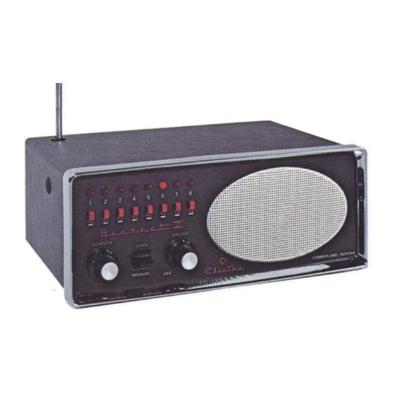
\\ith the porter cable and antenna properly connected,
turn the receiver O\
by rotating the "VOLUME"
conrol clockwise.
Place the B channel switches in the up (ON) position.
Set the
"\IA\UAL-SCA\"
switch on
"MANUAL".
Adjust the "SQUELCH" control clockwise until the
rushing noise is heard. Then adjust the "SQUELCH"
control counterclockwise until the rushing noise dis-
apPears.
Press the "MANUAL-SCAN" switch downward and
continue to step through all channels. If the noise
should "break the squelch" on any channel, adjust
the squelch control counterclockwise again slightly
to quiet the receiver. THIS MUST BE DONE BE-
TWEEN STATION TRANSMISSIONS.
The "MANUAL-SCAN" switch may now be used
to select and monitor any desired channel.
To sample all channels automatically, return the "MAN-
UAL-SCAN" switch to "SCAN".
Any channel may
be omitted as desired by moving the individual channel
switch downward (offl.
2.
6.
7.
- 3 -
