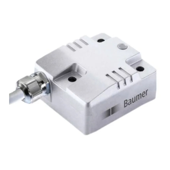
Baumer GIM500R Manual - Page 13
Browse online or download pdf Manual for Accessories Baumer GIM500R. Baumer GIM500R 13 pages. Inclination sensors
Also for Baumer GIM500R: Manual (20 pages), Manual (29 pages), Assembly Instructions (2 pages)

4
Terminal assignment and commissioning
Terminal assignment
4.1
M12 flange connector, 5 female contacts
Pin
Assignment
1
GND_GND
2
+Vs
3
GND
4
CAN_H
5
CAN_L
Terminals with the same designation are internally hardwired and identical in their functions. Maximum load
applied on UB-UB / GND-GND is 1 A each.
Activity indicator (DUO-LED)
4.2
A DUO-LED is provided at the sensor housing.
LED green
LED red
off
off
on
off
off
on
Baumer_GIM500R_SAEJ1939_MA_EN.docx
03.19
Description
Ground connection relating to CAN
Supply voltage
Ground connection relating to +Vs
CAN bus signal (dominant High)
CAN bus signal (dominant Low)
Activity / Significance
No power supply present
Operational Mode
error
13/13
M12 (male/female)
www.baumer.com
