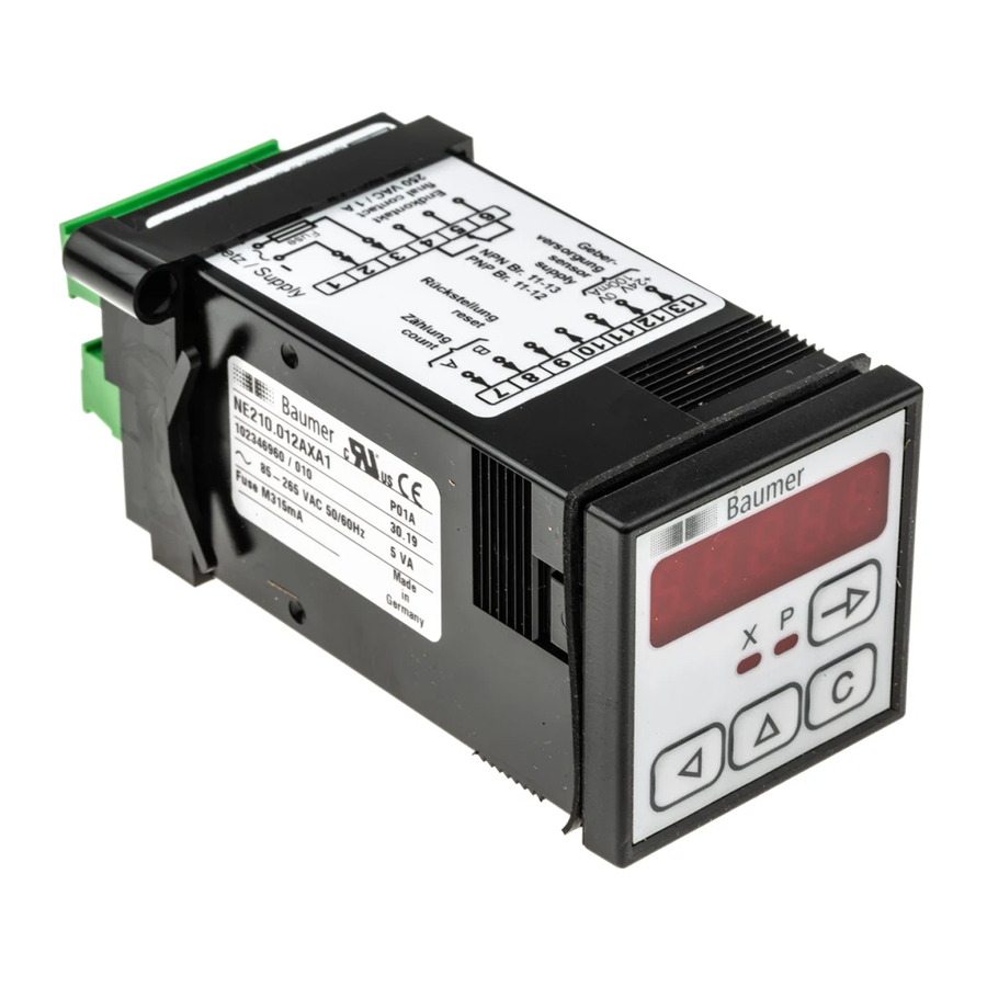
Baumer NE210 Operating Instructions Manual - Page 29
Browse online or download pdf Operating Instructions Manual for Cash Counter Baumer NE210. Baumer NE210 44 pages. Electronic preset electronic preset counter

NPN
K
B
E
PNP
E
B
K
Programming input logic The signal input logic can be programmed by means of a bridge
3.3
Assignment electronic output
The electronic output (terminal 10) is pre-programmed by the
factory as an NPN or PNP switching transistor (open collector) in ac-
cordance with the purchase order specification. The output is coded
as a pulse or continuous signal at DIP-switch 2.
Output logic
NPN
PNP
The electronic output is not short-circuit proof.
➔ Assign: terminal 10 accordingly.
3.4
Assignment signal input
Terminals 7 , 8 and 9 are optocoupler inputs that may be triggered by
any PNP or NPN encoder. The required input logic can be assigned at
the connecting terminal by wire jumper (refer also to assigning the
input logic.)
Specification of the inputs
Terminal 7
Terminal 8
NPN
PNP
Max. frequency
Input resistor
Stage Low
Stage High
Terminal 9
NPN
PNP
Min. impulse interval
Input resistor
Stage Low
Stage High
between terminals 11, 12 and 13, in accordance with the table below:
www.baumer.com
Max. voltage
+35 V
+24 VDC
Main counter counting input track A
Main counter counting input track B
Active with negative edge
Active with positive edge
10 kHz / 15 Hz
1.65 kΩ
0...0.8 V
14...27 V
Main counter reset
Active with negative edge
Active with positive edge
30 ms
3.3 kΩ
0...1.6 V
14...27 V
NE210
Max. current
50 mA
50 mA
29
