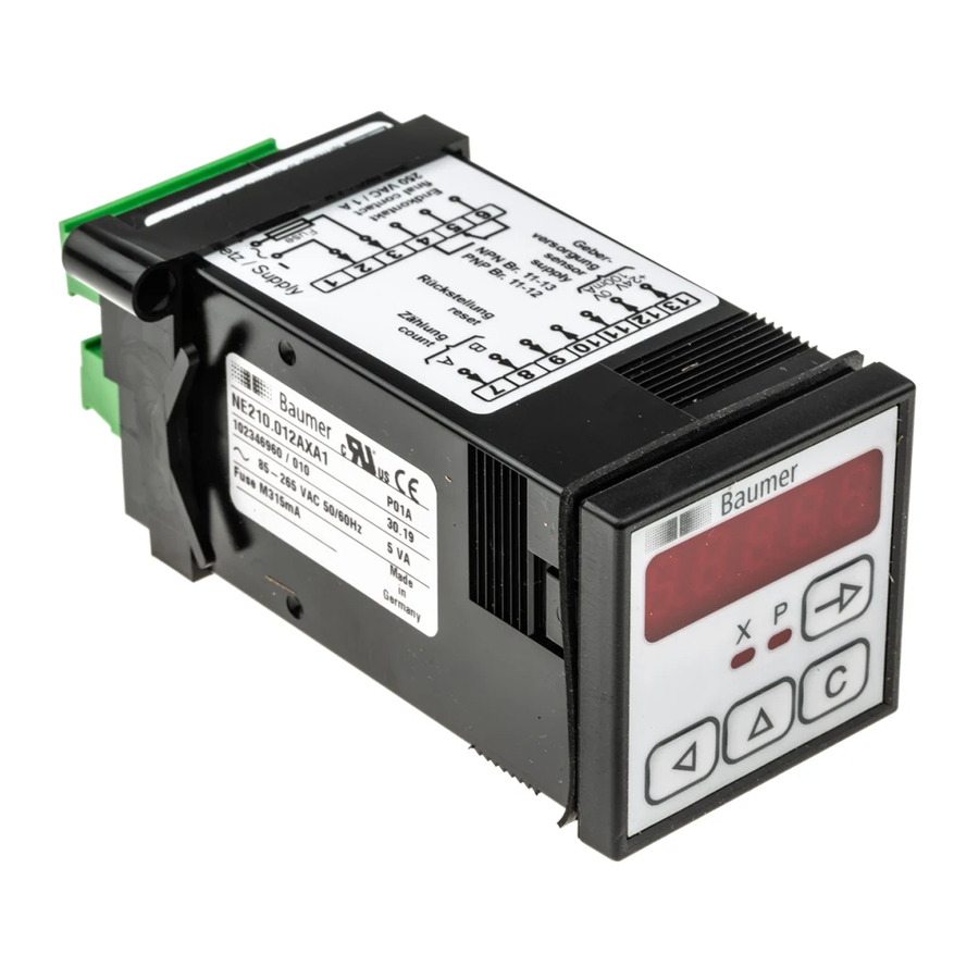
Baumer NE210 Operating Instructions Manual - Page 32
Browse online or download pdf Operating Instructions Manual for Cash Counter Baumer NE210. Baumer NE210 44 pages. Electronic preset electronic preset counter

NE210
32
3.5
Connecting the sensor supply
Connect the sensor supply at terminals 12 and 13 – for example en-
coder supply, etc.
Do not use the sensor supply to supply non-earthed inductive or
capacitive loads. The sensor supply is short-circuit proof (exception
model 24/48 VAC).
Voltage supply
24 VAC
48 VAC
85...265 VAC
24 VDC
With AC supply and PNP output logic the maximum permissible
sensor current will be reduced by the switching current of the
electronic output.
3.6
Establishing basic settings (DIP-switches)
The housing provides at rear four DIP switches to specify the main
basic device functions such as operating mode, kind of reset and
count frequency. Access to programming level for further optional
parameters is by DIP switch 4 (see chapter 5).
4
3
2
1
➔ Proceed the DIP switch settings prior to mounting the counter.
● Default upon delivery is all DIP switches to „OFF" .
DIP
OFF
1
Adding operating mode
2
Automatic reset
Output as impulse signal
3
Counting frequency 10 kHz
(exception A90°B x4 5 kHz)
4
Programming lock
www.baumer.com
Sensor supply
Current load
12...26 VDC
50 mA
12...26 VDC
50 mA
24 VDC ±20 %
100 mA
24 VDC ±20 %
100 mA
4
3
2
ON
Subtracting operating mode
External reset
output as permanent signal
Counting frequency 15 Hz for
contacts
Programming unlock
OFF
ON
1
