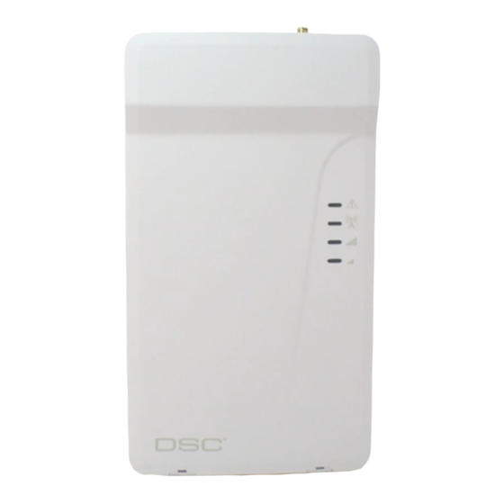
DSC LE4000 Installation Manual - Page 3
Browse online or download pdf Installation Manual for Cell Phone DSC LE4000. DSC LE4000 8 pages. Lte wireless alarm communicator

Introduction
The LE4000 is a cellular communicator that sends alarm system information to a Sur-Gard System I-IP, II, III, IV or 5 receiver
through an LTE or 3G wireless network. This cellular communicator can be used with UL/ULC Listed compatible control units,
as indicated in the manufacturer's installation instructions.
The performance of the LE4000 depends greatly on cellular network coverage. Therefore, it should not be mounted without
first performing placement tests to determine the best location for reception (minimum of one blue/green LED ON). Optional
antenna kits – LTE- 8ANT (8ft/2.4m), LTE-15ANT (15ft/4.6m), LTE- 25ANT (25ft/7.6m) and LTE- 50ANT (50ft/15.2m) are avail-
able.
NOTE: The LE4000 is designed to work with the Contact ID communication format as described in the SIA DC-05 standard, as
well as the SIA communications format as described in the SIA DC-03 standard. Before completing the field installation of the
alarm monitoring system please ensure communication with the supervising central station is successful by sending several
events and getting confirmation that they have been received.
Features
Penta-Band LTE; Dual-band UMTS (BII/V) and LTE (B2/4/512/13)Radio
l
Advanced Carrier Selection
l
Cellular Signal Indicator
l
LTE /3G / Internet communication with Sur-Gard SG-System I-IP / II / III / IV / 5
l
Compatible with 4-digit or 10-digit Contact ID communication format as described in SIA DC-05 Standard and the SIA DC-
l
03 standard for 300 baud. Example of suitable compatible alarm panels:
DSC Models HS2128, HS2064, HS2032, HS2016, PC1864, PC1832, PC1616, PC4020.
Panel Transmission Monitoring for up to four phone numbers
l
Simulates landline
l
Switches automatically to the LTE or 3G network in the event of landline trouble (e.g., line down)
l
DLS support for status, firmware updates and remote debug enable
l
Remote Firmware Upgrade
l
Remote Diagnostics
l
Case and Wall Tamper
l
Panel Format Detection
l
2 Programmable Inputs
l
2 Programmable Outputs
l
Technical Specifications
The input voltage to the LE4000 can be drawn from the UL/ULC Listed control panel or provided by an external UL/ULC Listed
power supply (with battery back-up) rated for the application (external power-limited source).
Power Supply Rating
Input Voltage Class:
Compatible External Power Adapters (2-
prong):
Input Voltage/ Input Current (Nominal):
Average Current:
Peak Current (no battery):
Peak Current (with battery):
Battery:
Battery Charging Voltage (maximum):
Battery Charging Current:
Battery Standby Time:
Class 2, power limited
DSC ADP1310(W)-NAU (US) / ADP1310(W)-NA (Canada)
NOTE: For UL/ULC listed installations, the input rating for the external
power adapter is 120V
AC
13.8V
/700mA (when supplied by compatible external power adapter)
DC
9-14V
/500mA (use listed, compatible control panel or power supply)
DC
40mA*
180mA*
350mA*
* Plus any curent draw from LE4000 + ve terminal
NiMH, rated 7.2V, 2.2Ah
9.1V
DC
160mA
24 hours
NOTE: Battery must be replaced every 3-5 years.
3
/60Hz/0.4A.
