DTM System DTM-SWIFT 350 Assembly Instructions For The Installer - Page 5
Browse online or download pdf Assembly Instructions For The Installer for Controller DTM System DTM-SWIFT 350. DTM System DTM-SWIFT 350 16 pages. Actuators for swing gates
1. Introduction
1.1. Basic information
Electromechanical actuators are designed to control swing gates. The assembled and started system
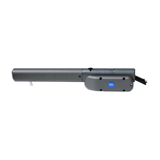
can be conveniently operated by radio transmitters. Make sure you have all the elements shown in Figure 1,
and then read the entire manual.
4
1
actuators
2
two elements fixing the actuator's piston to the gate fitting
3
two sets of elements fixing the actuator drive to the pillar fitting
4
manual
5
two keys for the drive clutch
6
two motor capacitors for actuators
7
screws for mounting drives in holders 2 and 3 with plugs
8
mechanical limit switch
Fig. 1. Necessary mechanical components.
1.2. Technical data of selected elements of the DTM300 / DTM400 / DTM600 set
housing material
•
mains supply (motor)
•
current consumption
•
power consumption
•
capacitor
•
maximum gate width
•
maximum gate weight
•
protection class
•
thermal protection
•
arm stroke
•
leaf movement speed
•
drawbar pull
•
lubrication
•
work intensity
•
temperature range
•
actuator weight
•
spacing of the actuator pin sockets min-max
•
1
7
5
2
6
8
aluminum with plastic parts
230V AC, 50Hz
1,6A
350W
8uF, 400V
3m
250kg
IP-44
o
150 C
350mm
12mm/s
2200 N
TS10
30%/h (18 cycles/h)
o
o
-20 C to +55 C
10 kg
476-826mm
3
1