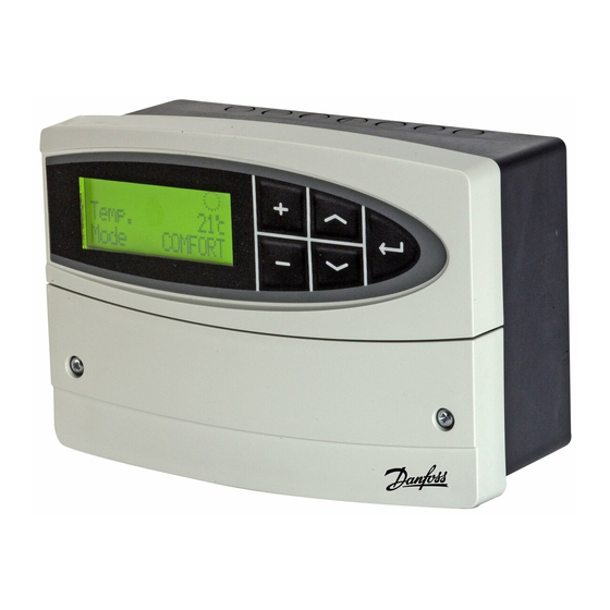
Danfoss ECL Comfort 110 User Manual, Installation & Maintenance - Page 13
Browse online or download pdf User Manual, Installation & Maintenance for Thermostat Danfoss ECL Comfort 110. Danfoss ECL Comfort 110 19 pages. Application 130
Also for Danfoss ECL Comfort 110: Datasheet (8 pages), Installation Manual (8 pages), Mounting Manual (8 pages), Quick Manual (2 pages), Quick Manual (2 pages), Quick Manual (2 pages)

Installation
Mounting the ECL Comfort controller
For easy access, you should mount the ECL Comfort controller near the system. Select
one of the three following methods:
•
Mounting on a wall
•
Mounting on a DIN rail
•
Mounting in a panel
Screws and rawlplugs are not supplied.
Mounting on a wall
Mount the controller on a wall with a smooth surface and establish the electrical
connections.
Mounting on a DIN rail
Mount the controller on the DIN rail and establish the electrical connections.
Mounting in a panel
Mounting kit: Order code no. 087B1249.
The panel plate thickness must not exceed 5 mm. Prepare a cut-out with the dimensions
93 x 139 mm. Insert the controller into the panel cut-out and fix it with the clamp which
is placed horisontally on the controller. Establish the electrical connections.
For further details on mounting, see the mounting guide.
24
VI.KT.F2.02
© Danfoss 06/2008
DH-SMT/DK
Electrical connections - 230 V a.c. - in general
* Optional connections for safety thermostat
Terminal
Description
20
Supply voltage 230 V a.c. - neutral (N)
21
Supply voltage 230 V a.c. - live (L)
22
Optional connections for safety thermostat
23
Optional connections for safety thermostat
24
M1
Actuator - open
25
M1
Actuator - close
26
M1
Actuator - neutral
27
P1
Circulation pump - neutral
28
P1
Circulation pump - live (relay R1)
29
Not to be used
30
Not to be used
2
Wire cross section: 0.5 - 1.5 mm
Incorrect connection can damage the TRIAC outputs.
VI.KT.F2.02
DH-SMT/DK
Max. load
15 VA
15 VA
4 (2) A
© Danfoss 06/2008
25
