Dataforth PWRM10-01 Quick Start Manual - Page 9
Browse online or download pdf Quick Start Manual for Control Unit Dataforth PWRM10-01. Dataforth PWRM10-01 20 pages. Iot energy monitoring modules

Figure 2: PWRM20-01 Installation and Removal from a DIN Rail
To remove a module:
5. Insert a flat blade screwdriver into the slot in the metal clip
6. Lift the screwdriver to pull back the clip and release the module from the rail
4.2 Wiring to Phase Voltages and Phase Currents
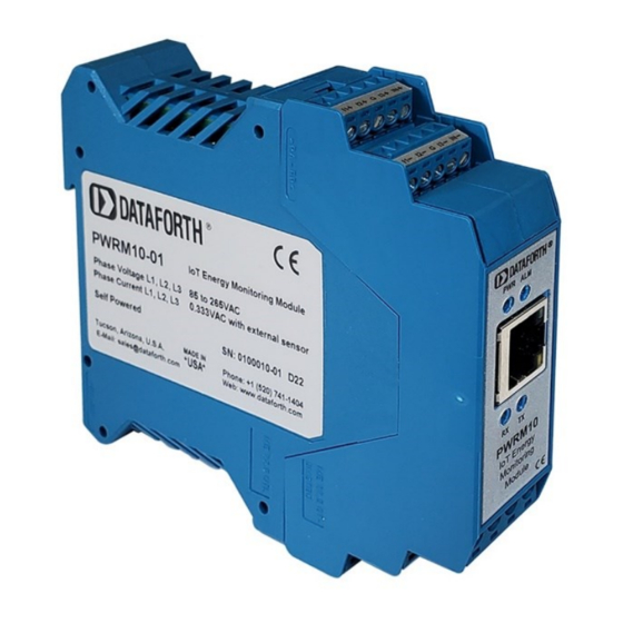
The PWRM10-01 and PWRM20-01 modules have pluggable terminal blocks to connect to phase
voltages and phase currents. This allows modules to be easily added to or removed from a system.
The modules are powered by the phase voltages and an external power supply is not required.
DANGER – HAZARDOUS VOLTAGES
These wiring instructions are for use by qualified personnel only.
Only licensed electricians or qualified personnel should install and maintain the modules and wiring.
REFER TO
MA1068 PWRM10-01 & PWRM20-01 Hardware User Manual
WIRING TO PHASE VOLTAGE AND FOR SENSORS AND WIRING TO PHASE CURRENTS.
PWRM10-01 and PWRM20-01 modules interface to phase currents with burden resistors, current
transformers, or Rogowski Coils with 0.333VAC output at rated current. This low voltage interface is
on the module top terminal blocks.
PWRM10-01 and PWRM20-01 modules interface to phase voltages using the bottom terminal blocks.
WARNING!
Mains voltages of 85VAC to 525VAC can be lethal!
MA1069 PWRM10-01 & PWRM20-01 Quick Start Guide
FOR DETAILS ON
Page 5 of 15
