DayTronic 3000PLUS Instruction Manual - Page 6
Browse online or download pdf Instruction Manual for Measuring Instruments DayTronic 3000PLUS. DayTronic 3000PLUS 20 pages. Panel meter, frequency conditioner module
Also for DayTronic 3000PLUS: Instruction Manual (20 pages)

cially noisy. Responding only to the modulated carrier
frequency, the module rejects extraneous voltages that
can cause errors in DC systems, particularly when
there is a need to "blow up" a portion of the transducer
range.
The conditioner's advanced analog design directly
addresses the problem of measurement inaccuracy in
industrial environments of high electromechanical
noise. Exceptional signal stability and accuracy over a
remarkably wide range of sensor inputs are achieved
through
• regulated, remotely sensed AC excitation
• precise linearity / symmetry correction and signal
phase adjustment via software commands
• high-stability amplification
• configurable low-pass active filtering
• "absolute" and "two-point" software-based
calibration
• effective signal isolation & ESD protection
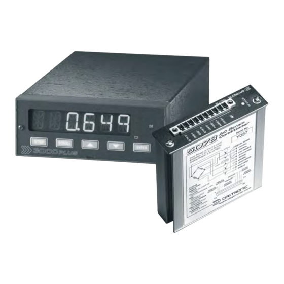
Plugging into the rear of the 3000PLUS meter, the 5D78
connects directly to its source strain gage sensor via
simple screw-terminal pinout (see Fig. 3). High output
accuracy over a wide temperature range guarantees
repeatable sensor signal integrity. For steady indication
and smooth, dependable control action, the conditioner
provides a true average value of the measured variable,
even in the face of substantial dynamic content.
The 5D78 features
• Powerful user-selectable low-pass active filter-
ing for removal of unwanted high-frequency mea-
surement-signal components and the elimination of
aliasing errors
• High noise rejection, eliminating errors from com-
mon-mode pickup and ground-loop coupling, with
1500 VAC isolation between input and output termi-
nals and between I/O and power supply / communi-
cations terminals
* Employing a low-capacitance cable will minimize the effects on
overall offset and span. See note (**) on page 1.4.
3000PLUS
5D78 I
WITH
1. I
NTRODUCTION
• High ESD immunity and extensive EMI protec-
tion further assure data integrity in harsh industrial
environments
Because of normal cable loading effects, it is a practical
necessity to calibrate any AC TORQUE SENSOR/
CABLE/INSTRUMENT system after installation, using a
known input standard. The "ABSOLUTE" CALIBRATION
method described in Sections 3.B and 4.E will normally
yield a very good first approximation for a sensor/
cable/5D78 system (depending, of course, on actual
cable length and capacitance).* However, absolute cal-
ibration of a 3000PLUS with installed Model 5D78
should always be followed by a conventional "in place"
TWO-POINT (DEADWEIGHT) CALIBRATION, for opti-
mum data integrity.
To perform initial ABSOLUTE CALIBRATION, you need
only use the front-panel menu or configuration software
to specify the desired relationship between the mod-
ule's measured engineering units and its ±5-VDC out-
put, given the full-scale input range for which it is
currently set and the source transducer's known full-
scale rating and sensitivity. A zero offset term may also
be entered, expressed either in engineering units or
millivolts.
TWO-POINT (DEADWEIGHT) CALIBRATION requires
the application of two independently and accurately
known values of input loading ("ZERO" and "SPAN"), fol-
lowing the entry of a phase shift adjustment. Activation
of a user-supplied shunt calibration resistor is provided
(for either a positive or negative upscale reading) for
use in the two-point method, if desired. Internal sym-
metry trimming is available for negative-domain slope
adjustments of up to ±2% of full scale, along with both
positive and negative midscale linearity correction.
M
NSTRUCTION
ANUAL V
. SB.3
3KP78 - 1.2
