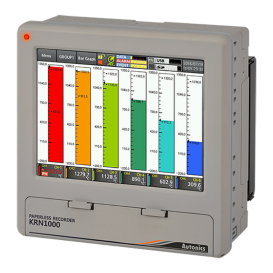
Autonics KRN1000 Series User Manual - Page 3
Browse online or download pdf User Manual for Measuring Instruments Autonics KRN1000 Series. Autonics KRN1000 Series 15 pages. Lcd touchscreen paperless recorder
Also for Autonics KRN1000 Series: Instruction Manual (2 pages), Instruction Manual (2 pages)

-|Transparent setting guide|-
KRN1000 Series
Input/Output
Type
Input/Output type
Input type
Universal input
Input impedance
Display
accuracy
Resolution
Digital input
Option
input/output
※ 3
Alarm relay
output
Power output for transmitter
RS422/485
Communication
Ethernet
output
※ 5
USB Device
※ 1. Current measurement and connection examples
Connect 250Ω shunt resistance and set analog input type 0-20mA (shunt) / 4-20mA (shunt).
It is available to measure 0-20mA / 4-20mA current.
※ 2.
At room temperature (23℃ ± 5℃)
RTD Cu50Ω (-200≤T≤200): (±0.1% F.S. or ±1.5℃, select the higher one) ±1 digit
RTD DPt50Ω (-200≤T≤500): (±0.1% F.S. or ±1.5℃, select the higher one) ±1 digit
Thermocouple R, S, C, G type (0≤T≤100): (±0.1% F.S. or ±4.0℃, select the higher one) ±1 digit
Thermocouple U, T type (-100≤T≤400): (±0.1% F.S. or ±2.0℃, select the higher one) ±1 digit
Thermocouple B type, below 400℃: there is no accuracy standards.
All thermocouples, below -100℃: (±0.3% F.S. or ±4.0℃, select the higher one) ±1 digit
Out of room temperature range
RTD Cu50Ω (-200≤T≤200): (±0.2% F.S. or ±3.0℃, select the higher one) ±1 digit
RTD DPt50Ω (-200≤T≤500): (±0.2% F.S. or ±3.0℃, select the higher one) ±1 digit
※ 3. Input/Output is different by option. Please refer to 「Ordering information.
※ 4. For supplying power for transmitter, it is recommended to use shield cable to reduce noise.
※ 5. RS422/485, Ethernet, USB device communication outputs are not used at the same time.
※ If sensor input line is longer, it is recommended to use shield cable to reduce noise.
U-6
Description
JPt100Ω, DPt100Ω, DPt50Ω, Cu100Ω, Cu50Ω
RTD
(supplied current: approx. 190µA)
Thermocouple
B, C (W5), E, G, J, K, L, L (Russia), N, P, R, S, T, U
Voltage: ±60mV, ±200mV, ±2V, 1-5V, ±5V, -1V-10V
Analog
Current: 0-20mA, 4-20mA (measurable when using 250Ω shunt
resistance)
Voltage (V): approx. 205kΩ
RTD, Thermocouple, Voltage (mV): min. 200kΩ
RTD
Warm-up time: Max. 30 min
Thermocouple
At room temperature (25℃±5℃): ±0.1% F.S.±1-digit
※ 2
Out of room temperature: ±0.2% F.S.±1-digit
Analog
16-bit
No-contact input
ON: residual voltage max. 1VDC, OFF: leakage current max. 0.1mA
Contact input
ON: max. 1kΩ, OFF: min. 100kΩ, Short-circuit: approx. 4mA
Capacity
250VAC
Mechanical: min. 20,000,000 operations
Life cycle
Electrical: 100,000 operations (250VAC
24±2VDC , max. 60mA ※ Built-in over current protection circuit
※ 4
Modbus RTU ※ It is recommended to use shielded cable over AWG 24.
IEEE802.3 10 BASE-T / IEEE802.3U 100 BASE-TX (Modbus TCP)
USB V2.0 Full Speed (Modbus RTU)
※ 1
3A, 30VDC
3A, 1 Form A (resistive load)
3A, 30VDC
3A)
