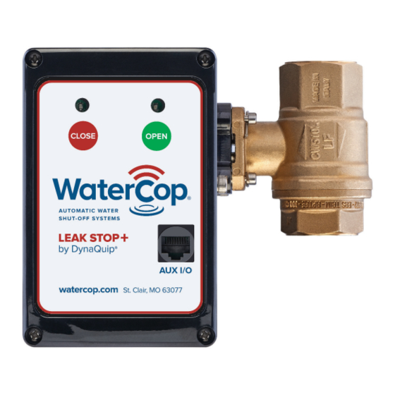
DynaQuip WaterCop LEAK STOP+ Owner's Manual And Installation Manual - Page 7
Browse online or download pdf Owner's Manual And Installation Manual for Control Unit DynaQuip WaterCop LEAK STOP+. DynaQuip WaterCop LEAK STOP+ 13 pages.

Sensor Placement
Place the attached sensor probes in the areas where water would fi rst accumulate
if a leak occurs.
Note: Care should be taken to place the sensor probe fl at on the fl oor so water can
be detected as soon as it begins to accumulate. The gold pins should not come in
contact with any other objects or the fl ooring surface.
Sensors should be taped or adhered directly to the fl oor or pan under the monitored
appliance, however extreme care should be taken to avoid:
1. tape or adhesive touching or hindering
water reaching the gold pins;
2. the gold pins do not come into contact
with metal or other conductive services.
This may cause a false alarm of the system.
System Operation
Leak Stop
The WaterCop®
moisture. When water comes in contact with the sensor probe, the
control box will close the valve, shutting off the local water supply. The valve will
remain closed until it is manually reset using the green button on the
control box. Lights on the
(Red = Closed, Green = Open).
Leak Stop
The WaterCop®
event using the open/close buttons on the front of the actuator.
Leak Stop
The WaterCop®
outlet. In the event of power failure, the
position. When power is restored, the valve remains in current position.
Water level
+
constantly monitors the selected area for accumulating
+
Leak Stop
control box also indicate valve position
+
valve may be controlled independent of a water leak
+
requires an uninterrupted standard 120 VAC household
Leak Stop
Sensor placed at a low spot
in the path of water fl ow where
it will make contact with sensor.
Probe
Leak Stop
+
valve will remain in current
+
+
Leak Stop
7
