Galletti estro classic Installation, Use And Maintenance Manual - Page 4
Browse online or download pdf Installation, Use And Maintenance Manual for Air Conditioner Accessories Galletti estro classic. Galletti estro classic 8 pages.
DECLARATION OF CONFORMITY
Galletti S.p.A. with head office in via Romagnoli 12/a, 40010
Bentivoglio (BO) - Italy, declares herewith under its own responsibility
that the CL estro classic fan coil units, terminal units for air-
conditioning and heating systems, are produced in accordance
with EEC Directives 2006/42/CE, 2004/108/CE, 2006/95/CE and
subsequent modifications.
Bologna, 27/05/2010
GB
Luca Galletti
President
SAFETY SYMBOLS
Carefully read this handbook
1
BEFORE THE INSTALLATION
Carefully read this handbook.
Installation and maintenance should be carried out by technical
personnel qualified for this type of machine, in compliance with
current safety regulations.
This appliance is not intended to be used by children or
persons with physical, sensorial or mental problems, inexpert
or unprepared, without supervision.
Be careful that children do not approach the appliance.
When receiving the unit please check its state verifying if any damage
occurred during the transport.
For installation and use of possible accessories please refer to the
pertinent technical sheets.
Identify model of the estro classic fan coil from the indications stated on
the carton package.
2
USE AND OPERATING LIMITS
Galletti S.p.A. shall not be held liable where the unit has been installed by
non-qualified personnel, it has been used improperly or under conditions
that are not permitted, the maintenance operations specified in this manual
have not been carried out or where non original spare parts have been
used.
Operating limits are shown here below; all other uses are
considered improper:
- thermal fluid: water
- water temperature: from 5°C to 95°C
- maximum operating pressure: 10 bar
- air temperature: from 5°C to 43 °C
- power supply: 230V +/- 10%
In choosing where to install the unit, comply with the following points:
- do not install the unit in rooms where inflammable gases are present
- do not let water is sprayed directly on the unit;
- install the unit on ceilings or walls that bear its weight. Leave enough
space all around for proper operation and maintenance of the unit.
Keep the unit in its packaging until it is ready to be installed, to prevent dust
getting inside it.
3
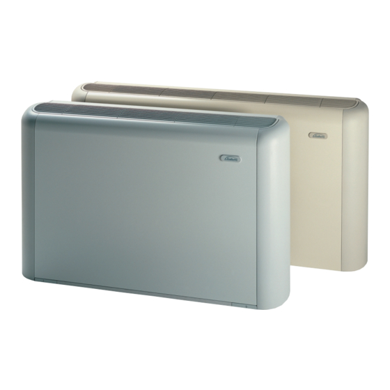
DESCRIPTION OF THE UNIT (figure 1, page 6)
Fan coil units for wall installation, with cabinet and vertical air outlet
4
DIMENSIONS (figure 2, page 6)
1
Space for hydraulic connections
2
Slots for wall-mounting
3
Space for electrical connections
4
Standard heat exchanger hydraulic connections
4DF
DF 1-row additional heat exchanger hydraulic connections
5
Condensate discharge
FC66000962 - 02
È severamente vietata la riproduzione anche parziale di questo manuale / All copying, even partial, of this manual is strictly forbidden
DANGER
ATTENTION
VOLTAGE
5
INSTALLATION
WARNING:
On the fan-coil install a switch (IL) and/or all remote controls in
a position out of the reach of persons who are in a bathtub or
shower.
Remove the cabinet by unscrewing the 4 fastening screws reachable through
the lifted side doors (figure 3, page 6).
Fix the bearing unit to the wall using the 4 mounting slots and the supplied
anchor screw, keeping the unit at least 100 mm above the floor for a proper
air intake and an easy removal of the filter.
Carry out the hydraulic connections to the heat exchanger and in case of
cooling operation, to the water drainage system.
We suggest to provide the water inlet from the bottom side of the heat
exchanger and the outlet on the upper side.
Bleed the air from the heat exchanger operating on the air-vent valves (10
hexagon wrench) located beside the water connections of the heat
exchanger.
For a better water drainage lean the drain pipe downwards at least 3 cm/
m avoiding loops or narrowing on its way.
5.1
ROTATION OF THE HEAT EXCHANGER
It is possible to orient the attachments of the heat exchanger on the
opposite side operating as follows:
- remove the front panel of the bearing unit (4 screws);
- remove the sheet of the heat –exchanger cover (2 screws);
- remove the heat exchanger (4 screws) fixed on the side panels of the
bearing unit;
- remove the lower baffle;
- disconnect the motor cables from the terminal strip;
- remove the terminal strips and reassemble it on the opposite side;
- take out the motor cable and place it on the opposite side; remove the
rubber raceway;
- remove the drain pipe and place it on the opposite side; set the drop
breaker pipe in the place of the closing cap of the drip tray;
- turn the heat exchanger 180°;
- reassemble the baffle on the bottom side;
- insert the attachments into the specific openings by removing the pre-
cut slots and then fix it to the unit using the screws supplied;
- reassemble the sheet of the heat exchanger cover;
- insert the rubber raceway into the hole previously used for the drain pipe,
reassemble the cable fastener on the side panel, insert the cables
connecting them to the terminal strip;
- reassemble the unit's front panel (4 screws);
- close the holes previously used with drip proof material.
5.2
ELECTRICAL CONNECTIONS
Carry out the electrical wiring after having turned the power off in
compliance with the current safety regulations following the
diagram of the figure 4 and its caption.
Check that the power supply corresponds to the rated power reported
on the unit nameplate.
Each fan-coil requires a switch (IL) on the feeder line with a distance of at
least 3 mm between the opening contacts, and a suitable safety fuse (F).
On the wiring diagram the following abbreviations are used:
BK
BU
CN
F
GNYE
Yellow/Green = earth
IL
Line switch, not supplied
M
RD
WH
1
Connection to the control panel (accessory)
Electric connections in dotted lines should be carried out by the installer.
4
Black = max. speed
Blue = medium speed
Fast-on connector
Fuse, not supplied
Motor
Red = min. speed
White = common