Galmet SGW(S) Maxi 300 Installation And Operating Manual - Page 3
Browse online or download pdf Installation And Operating Manual for Water Heater Galmet SGW(S) Maxi 300. Galmet SGW(S) Maxi 300 20 pages.

1. Device description
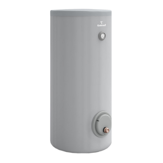
The main part of the heater is a hot water tank that is made of sheet steel covered with vitreous enamel. The usable warm water heater is equipped with
high capacity heating coil designed for heat pumps as well as for high power central heating boilers. The holes in the tank bottoms are plugged. Cold water
supply connections from the water supply and hot usable water disposal are located on one side of the heater's body. In addition, an opening for connecting
the circulation and a temperature sensor has also been provided. The tank is equipped with two magnesium anodes: one is positioned in an inspection hole
(screw M8), and the second one is located in the upper bottom plate (5/4" plug for 250-500 l capacities and 2" plug for 700-1000 l capacities).
1.1. Remember
1. Before installation of the heater it is recommended to read the installation and user manual that comes with the device.
2. Do not start using a water heater that is not filled with water.
3. Do not operate the internal DHW heater and the external boiler water heater without a fully operational relief valve (proper functioning of the relief
valve must be checked every 14 days by turning its cap left or right to induce an outflow of water from a discharge port located on the side of the valve.
Following that, turn the cap in the opposite direction until it snaps in place and press down to the valve body. If there is not outflow of water while turning
the cap, the valve is not operational. A continuous outflow of water after returning the cap to its previous position indicates valve head contamination.
In such a case, flush the valve several times by turning the cap to open the outflow of water. Caution - there is a possibility of hot water outflow. The
company will not be responsible for improper functioning of the relief valve caused by wrong installation or errors within the system, e.g. missing a
pressure reducing valve in the cold water removal system. For the DHW storage tank, maximum pressure of full opening of relief valve must not exceed
0,67 MPa, whereas for boiler water tank, maximum pressure of full opening of relief valve in a closed system must not exceed 0,35 MPa.
4. Proper protection of a boiler operating with the heater guarantees proper protection of the heating coil in the heater.
5. At least once a year have the heater flushed by a specialised contractor.
6. At least once every 18 months replace the magnesium anode in the DHW tank - not covered by warranty.
7. Eliminate contamination by using filters to extend the service life of the tank and ensure proper functioning of the relief valve.
8. If tanks operate in a very aggressive environment (e.g. in a cow-house etc.), purchase a product specifically prepared for use in such an environment (the
Manufacturer will prepare parts susceptible to accelerated corrosion by providing chemical protection).
9. Do not prevent water from dripping from the relief valve – do not plug the discharge port of the relief valve. If water continuously leaks from the relief
valve, it indicates that the water main system pressure is too high, or that the relief valve is defective. Discharge port of the relief valve should be oriented
downwards. It is recommended to place a funnel underneath the relief valve to collect and drain water. A hose can also be fitted over the discharge port
to remove water flowing when the relief valve is being opened. The hose should be heat resistant up to +80°C, with internal diameter of 9 mm and max.
length of 1,2 m, run to a drain with a downgrade (min. 3%) in an environment of temperature not lower than 0°C. The hose must be protected against
bottlenecking (squeezing, plugging) and its discharge end should be visible (in order to verify operation of the valve).
10. „Galmet Sp. z o. o." Sp. K. reserves the right to introduce any modification without prior notification.
11. The heating coil should be flushed by the installer before the first use (besides, installing a filter is recommended to remove any impurities). If the heating
coil is not used (e.g. due to the use of an electric resistance heater), it must be completely filled with an appropriate glycol mixture in order to prevent
corrosion caused by condensed water. After filling, the heating coil must not be closed on both sides (thermal expansion of air).
12. The tank has an outer casing made of artificial leather (skay, PVC foil), while the thermal insulation is made of polyurethane or polystyrene foam. It is not
allowed to manipulate open fire directly next to the tank, as it may damage the outer casing as well as the thermal insulation.
13. All maintenance and installation works must be performed in accordance with applicable health and safety regulations.
14. Unpleasant scents and darkening of the water from the heater may be the result of a hydrogen sulphide, which is formed by reducing the sulphate
content of bacteria that live in oxygen-free water. If cleaning the tank, replacing the magnesium anode and starting with a temperature above 60°C will
not yield result, we recommend using a titanium anode.
15. If the heating coil is not used (e.g. due to the use of an electric heater), it must be completely filled with a suitable glycol mixture to prevent corrosion
caused by condensed water. After filling, the coil cannot be closed on both sides (air expansion by temperature).
© All rights reserved - Galmet Sp. z o.o. Sp. K.
Installation and Operating Manual / Warranty Card - SGW(S): Maxi / Maxi Plus / M
1. Device description
3
