Dynojet power commander III Instalation Instructions - Page 2

Browse online or download pdf Instalation Instructions for Automobile Accessories Dynojet power commander III. Dynojet power commander III 3 pages. 2004 kawasaki zx12r
Also for Dynojet power commander III: Installation Instructions (5 pages), Installation Instructions (5 pages), Installation Manual (3 pages), Installation Instructions (4 pages), Installation Manual (3 pages), Installation Instructions (4 pages), Installation Instructions Manual (3 pages), Installation Instructions (3 pages), Instalation Instructions (3 pages)
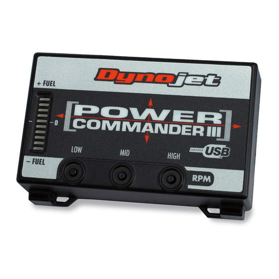
Dynojet power commander III Instalation Instructions
Separate this
connector
Connectors from
Power Commander
Stock connectors
Locate wire and connector
from rear brake light switch
i206-411
www.powercommander.com
1)
Remove the passenger seat or solo
seat cover section.
2)
Remove the main seat.
3)
Remove the fuel tank shell and prop
the front of the fuel tank up.
4)
Disconnect the fuel injector connector
shown in Fig. A. This connector is
located on the backside of the frame
towards the bottom of the fuel tank.
There are two connectors side by side,
disconnect the one on the left.
5)
Plug the connectors from the Power
Commander in line of these connec-
tors. (Fig. B)
6)
Disconnect the rear brake light con-
nector. (Fig. C)
2002-2003 Kawasaki ZX-12R - PCIII USB - 2