Dea ghost 200 Operating Instructions And Warnings - Page 4
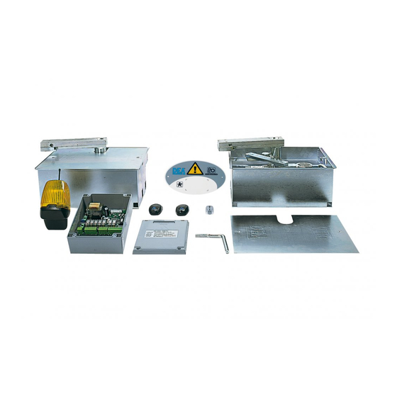
Browse online or download pdf Operating Instructions And Warnings for Gate Opener Dea ghost 200. Dea ghost 200 17 pages. Underground electro-mechanical operator for swing gates
Also for Dea ghost 200: Operating Instructions Manual (16 pages)

"LENGTH-WEIGHT" chart
Kg
1000
stop
fast
750
500
250
0
1
WARNING The use of the product under unusual conditions
not foreseen by the manufacturer can create situations of dan-
ger, and for this reason all the conditions prescribed in these
instructions must be respected.
WARNING Under no circumstances must the product be
used in explosive atmospheres or surroundings that may prove
corrosive and damage parts of the product.
4.5
Instructions for risk-free operation
4.5.1 Transport
The GHOST 200 gate operator is always delivered packed
in boxes that guarantee the product adequate protection. Care-
fully read any warnings or instructions for storage and handling
provided on the box.
4.5.2 Installation, assembly and disassembly
The following operations are essential to the correct laying
of the product:
• the careful definition of the entire automatic opening layout
(see also "6 Complete Closing Assembly"); in particular,
after carefully assessing the characteristics of the place you
have selected, define the model and the correct positioning
of the foundation box. (see F2, F3, F4 Page 30 e 31);
• dig a hole and position the foundation box (see F4, page 30);
• check carefully the correct positioning of the foundation box;
• put the foundation box in concrete;
• position the gate and weld the lever unit to the gate;
• cover with the foundation box protective lid.
MALFUNCTION
When the opening command
is given, the gate wing fails
to move and the operator's
electric motor fails to start
When the opening command is
given, the motor starts but the
gate wing fails to move
The operator jerks or is noisy
during movement
Operating instructions and warnings
electric lock
slow
m
2
3
4
A1
A2
"TROUBLE-SHOOTING" table
The operator is not receiving correct power supply. Check all connections, fuses, and the
power supply cable conditions and replace or repair if necessary
Check that the unlocking system is closed (see F8, page 32)
Make sure that the electronic device for power adjustment is in good condition
Check if the gate pushes while closing; the motor electrical connections might be inver-
ted
If the wing of the gate does not move freely, release the piston and readjust the rotation
points
Make sure that the electronic device for electric power adjustment is in good condition
The power of the gearmotor may be insufficient for the characteristics of the gate's wing;
check the choice of model whenever required
WARNING All installation, maintenance, cleaning or repair
operations on any part of the system must be performed exclu-
sively by qualified personnel with the power supply discon-
nected working in strict compliance with the electrical standar-
ds and regulations in force in the nation of installation.
The necessity of installing reinforcement plates must always
be carefully assessed, whenever the remaining part of the struc-
ture does not appear sufficiently strong, whenever the metal
plate used does not appear thick enough or whenever the mor-
phology of the gate appears to lack solidity.
Keep all welding seams well protected from corrosion.
Give extra attention to the alignment of the attachments and
their correct vertical positioning.
4.5.3 Starting
The installation of the product requires masonry and/or wel-
ding and electrical connection operations using adequate equi-
pment for the job in complete respect of the accident-prevention
standards and regulations in force in the nation of installation.
The product must be electrically connected to a special con-
trol unit for gate operators; see the instructions provided for such
device for further information.
4.5.4 Use
The product is designed for incorporation in the assembly of
devices that comprise the gate's automatism. DEA System assu-
mes that it will always be used in compliance with the standards
and regulations in force.
All GHOST 200 models have an unlocking system; the
working of this system is the following: Once you have unlocked
with a special key the spring device contained in the lever unit,
the operator is released and, if no other obstructions are pre-
sent, the gate is free to move without hindrance. The opposite
procedure, in other words, positioning the gate on the lever unit
and blocking the spring device with the apposite special key, re-
turns the GHOST 200 operator to normal working conditions.
WARNING Starting the operator with the lever unit set on the
released position may severely injure your arms and legs. Be
extremely careful! Release the lever unit only if really neces-
sary: If there is a power supply failure disconnect manually the
power supply of the operator by using the apposite switch; in
this way, when the power is back you will be able to start the
operator only after blocking the lever unit again.
CAUSES / SOLUTIONS
GH OS T 200
A3
A4
9
