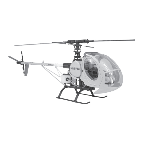
Century Helicopter Products Schweizer 300 Scale Instruction Manual - Page 8
Browse online or download pdf Instruction Manual for Toy Century Helicopter Products Schweizer 300 Scale. Century Helicopter Products Schweizer 300 Scale 12 pages.

Step 14
The tail boom, tail pushrod guides and tail boom supports should be painted at this time before assembly.
Remember that the pushrod guides may need to have the
side holes sanded slightly larger to fit the painted tail
boom.
At Step 28, dis-assemble the tail pitch plate assem-
bly by removing the lock ring carefully and re-
verse the pitch plate (part between the ball bearing
and the tail pitch ball links). Reassemble the parts
and epoxy or JB Weld the lock ring in place.
At Step 32, mount the bellcrank with the pitch plate
assembly engaged. While assembling the tail rotor
grips, examine the individual grips, one half has the
recess molded for the 2mm nuts. This half of the grip has
to be facing away from the gearbox when complete. Wait
until the next step to attach the tail rotor blades.
At Step 35, the tail pushrod guides have to be installed on the tail
boom in the correct order with the strut and fin mounts. Starting from
the tail gearbox, two fin mounts, one pushrod guide, two more fin mounts, one pushrod guide, one strut
mount, one pushrod guide, and lastly one strut mount. Position the gearbox halves over the tail boom so the
tail rotor assembly is on the left side of the helicopter (this is opposite to the Hawk instruction manual). In this
position the tail pitch bellcrank will be on the top along with the pin from the pitch plate, tighten the gear box
bolts and remove the original vertical and horizontal fin. Now while turning the main gear clockwise (the
direction of rotation), attach the tail rotor blades with the leading edge on the same side of the ball on the tail
blade grip as shown in the photo.
Step 15
Drill two 1/8" holes through each fin at the locations
marked in the recesses. Using two 3x10mm Socket Cap
Screws and 3mm locknuts attach the rear straight fin
closest to the tail gearbox at a 45 degree angle. Do not
overtighten these screws as you will damage the tail fins.
Slide a tail pushrod guide in-between and mount the
vertical tapered fin straight down at 2" infront of the first
fin. Bend the 9" tail wire in a large radius as shown,
remove the locknut on the lower mount (previously for the
vertical fin) and attach one 3mm hex nut using threadlock,
next thread the machined standoff on the bolt until the
bolt is just visible through the vertical hole, slide the tail
wire in place and secure using one 3x4mm set screw using threadlock. Position the wire to run vertically
down while the curving backwards.
7
in-
Nut side of
blade grip
face out-
wards.
Ball is on the
trailing edge of the
rotor blade.
Tail pitch
plate
change.
Use threadlock
on the set screw.
