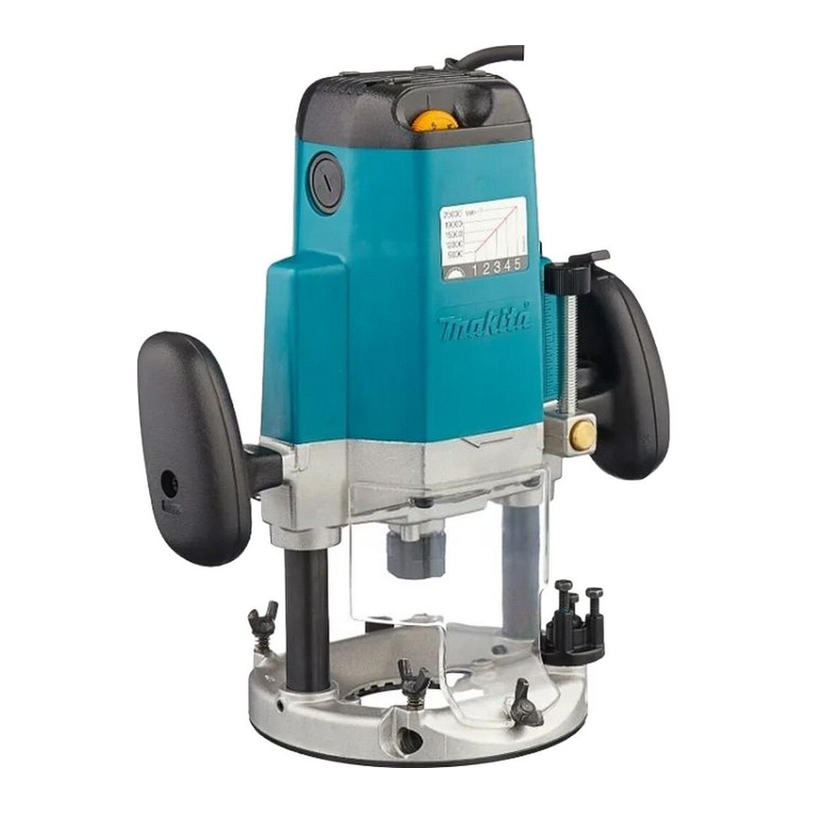
Makita 3612 Instruction Manual - Page 6
Browse online or download pdf Instruction Manual for Power Tool Makita 3612. Makita 3612 20 pages. Guide rail adaptor
Also for Makita 3612: Parts Breakdown (3 pages), Instruction Manual (16 pages)

1
4
1. Stopper pole
2. Hex bolt
3. Hex nut
4. Stopper block
1. Switch lever
1
2
1. Lock-off button
2. Switch trigger
1
1. Speed adjusting dial
6
Stopper block
003657
The stopper block has three adjusting hex bolts which raise or lower 0.8 mm
per turn. You can easily obtain three different depths of cut using these adjust-
ing hex bolts without readjusting the stopper pole.
Adjust the lowest hex bolt to obtain the deepest depth of cut, following the
method of "Adjusting depth of cut". Adjust the two remaining hex bolts to
obtain shallower depths of cut. The differences in height of these hex bolts are
2
equal to the differences in depths of cut.
3
To adjust the hex bolts, first loosen the hex nuts on the hex bolts with the
wrench and then turn the hex bolts. After obtaining the desired position,
tighten the hex nuts while holding the hex bolts in that desired position. The
stopper block is also convenient for making three passes with progressively
deeper bit settings when cutting deep grooves.
Switch action
For tool without lock-off button
003660
CAUTION:
•
Before plugging in the tool, always check to see that the tool is switched
off.
1
•
Make sure that the shaft lock is released before the switch is turned on.
•
Hold the tool firmly when turning off the tool, to overcome the reaction.
To start the tool, move the switch lever to the I (ON) position. To stop the tool,
move the switch lever to the O (OFF) position.
For tool with lock-off button
005066
CAUTION:
•
Before plugging in the tool, always check to see that the switch trigger
actuates properly and returns to the "OFF" position when released.
•
Make sure that the shaft lock is released before the switch is turned on.
To prevent the switch trigger from being accidentally pulled, a lock-off button is
provided
To start the tool, push in the lock-off button and pull the switch trigger. Release
the switch trigger to stop.
Speed adjusting dial
For model 3612C only
003802
The tool speed can be changed by turning the speed adjusting dial to a given
number setting from 1 to 5.
Higher speed is obtained when the dial is turned in the direction of number 5.
And lower speed is obtained when it is turned in the direction of number 1.
This allows the ideal speed to be selected for optimum material processing,
i.e. the speed can be correctly adjusted to suit the material and bit diameter.
Refer to the table for the relationship between the number settings on the dial
and the approximate tool speed.
