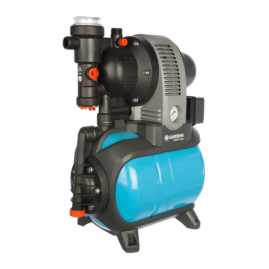
Gardena 1753 Operating Instructions Manual - Page 5
Browse online or download pdf Operating Instructions Manual for Water Pump Gardena 1753. Gardena 1753 17 pages. Pressure tank unit

Connect the hose to
the suction side:
Art. 1723 /
Art. 1724
6
4
5
Connect hose to the
output side:
8
A vacuum-tight suction hose must be used e. g.:
– GARDENA Suction Unit Art. no. 1411 / 1418 / 1412 or
– GARDENA Bore Hole Suction Hose Art. no. 1729.
Do not use any water hose snap connection system components
on the intake side!
v Connect the suction hose
connection
Connect the suction hoses
a connection piece (e.g. Art. no. 1723/1724)
side connection and screw in place so that they are airtight.
To reduce the pump repriming time, we recommend using
a suction hose with backflow preventer, which prevents the
suction hose emptying automatically when the Pressure Tank Unit
is switched off.
For suction heights exceeding 4 m also secure the suction hose
(e. g. by fastening it to a wooden post) to relieve the pump of the
weight of the suction hose.
If very fine dirt is present in the pumping medium, we
recommend the use of a GARDENA Pump Preliminary Filter
Art. no. 1730 / 1731.
Note:
Use pressure-tight GARDENA hoses, 19 mm (3/4") in diameter,
in connection with the GARDENA Quick-Release Threaded
Connector with 33.3 mm (G1) internal thread, Art. no. 7109,
7
and the GARDENA Suction and High Pressure Connector,
Art. no. 7120, for 19 mm (3/4") hoses and a GARDENA Hose
Clip, Art. no. 7192.
Under no circumstances use these hoses on the suction
side.
v Connect delivery hose
v Tip: If permanent pipes are installed, they must be laid at an
ascending angle in order to allow the water to flow back into
the pump on the pressure side.
5
with the intake side
6
of the pump.
5
without a threaded connector via
7
to the delivery side connection
4
with the intake
5
8
.
15
