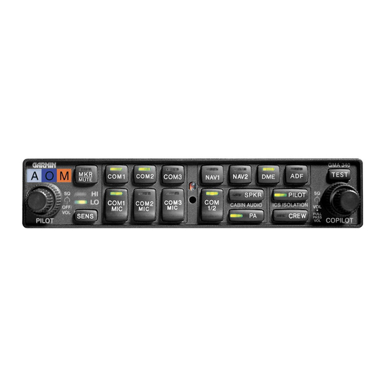
Garmin GMA 340 Pilot's Manual - Page 2
Browse online or download pdf Pilot's Manual for Avionics Display Garmin GMA 340. Garmin GMA 340 4 pages. Audio panel
Also for Garmin GMA 340: Pilot's Manual (12 pages), Supplemental Operation Manual (10 pages), Pilot's Manual (8 pages), Installation Manual (43 pages), Pilot's Manual (8 pages), Pilot's Manual (12 pages)

Front
Panel
Controls
Marker
Beacon
Marker
Beacon
Marker
Beacon
Marker
Beacon
Passenger
].1.
Passenger
Address (PA)
Function Button
I2.
Speaker
Function Button
Transceiver
Audio
Selector
Buttons
(COMl,
COM2, COM3)
Transmitter
(Audio/Mic)
Selection Buttons
Split
COM
Buuon
Aircraft
Radio
Audio
Selection
Buttons
(NAVI,
NAV2, DME, ADF)
I7.
Annunciator
Test
Button
18.
Locking
Screw
Access
19.
Photocell - Automatic Annunciator
Dimming
On, Off, and
Fail-Safe
Operation
The GMA 340
is
powered off when the left small
knob (5)
is
rotated
tully
CCW
into
the detent.
To
turn
the
unit
on,
rotate the
knob
clockwise
past
the
click.
The
knob
then functions
as
the
pilot
ICS volume
control.
A
fail-safe
circuit
connects
the
pilot's
headset
and microphone directly
to
COMI
in
case
power is
interrupted or
the
unit
is
turned
off.
Lighting
LED
button annunciator and marker
beacon
lamp intensity
are
controlled automatically by
a
built-in
photocell on
the
front
panel.
Nomenclature
backlighting
is
controlled by
the aircrafr
dim-
mer
buss.
Transceivers
Audio level is controlled by
the
selected C0M radio volume controls.
Selection of either
COMI,
COM2,
or COM3
for
both MIC
and audio
source is
accomplished by
pressing
either
COMI
MIC, COM2
MlC, or
COM3
MIC
(la).
The
acrive
COM audio is
always
heard
on
the
headphones.
Additionally,
each
audio
source can be selected
independently by
pressing
COMI,
COM2, or
COM3
(13).
When
selected
this
way,
they remain active
as
audio
sources regardless
of
which
trans-
ceiver
has been selected
for
microphone
use.
When
a
microphone is
keyed,
the
active transceiver's
MIC button
LED blinks
approximately
once per second
to
indicate
that
the radio
is
transmitting.
Split
COM
Pressing
the
COM
I/2
button
(15)
activates
the
split COM
function.
When
this mode
is
active,
COMI
is
dedicated solely
to
the
pilot
for
MlOaudio while
COM2 is
dedicated
to the copilot for
Ml0audio.
The
pilot
and copilot
can simultaneously
transmit
in
this
mode over
separate
radios.
Both
pilots
can
still
listen to COM3,
NAVì,
NAV2, DME, ADE and MKR
as
selected. The
split
COM
mode
is
cancelled
by
pressing the
COM
l/2
bunon
a
second rime.
When in
the
split COM
mode the
copilot
may make
PA
announcements
while
the
pilot contin-
ues
using
COMI
independently. When the
PA
button
is
pressed
after the
split com
mode is acri-
vated, the copilot's
mic
is
output
over the cabin
speaker
when
keyed.
A second
press
of the
PA
but-
ton
retums the
copilot to
normal
split COM
operation.
@@
NAV
2
=:
SPKR
=:PILOT
AUOIO
tsoLATtot{
:CREW
L-amps
Receiver
Audio
Select/Mute
Button
Receiver
Sensitivity Indicator
LED.
Receiver
Sensitivity
Selection
Button
/Þ
o
v9.
I.
MKR
2
BCN
3
4.
5.
Unit On/Olf, Pilot
Intercom
System
(lCS)
Volume
6.
Pilot
ICS Voice
Activated (VOX) Inte¡com
Squelch
7.
Copilot and
Passenger
ICS Volume
Control
(Pull
Volume)
8.
Copilot/Passenger
VOX
Inte¡com
Squelch Level
9.
Crew Isolation Intercom Mode Button
I0.
Pilot
Isolation Intercom Mode Button
Level
out
for
rcs
I
r3.
COM/
14.
NAV
15.
16.
s-lHt
Q::
to
